Supercharge Your Innovation With Domain-Expert AI Agents!

Compression mold with charging structure

The technology of a compression molding mold and a buckle structure is applied in the field of compression molding molds, which can solve the problems of large consumption of manpower and material resources, and achieve the effects of saving labor, saving time, and eliminating the step of reclaiming materials.

Pending Publication Date: 2018-11-16
南京华腾汽配有限公司
View PDF6 Cites 0 Cited by
  • Summary
  • Abstract
  • Description
  • Claims
  • Application Information

AI Technical Summary

Problems solved by technology

High consumption of manpower and material resources

Method used


Image

  • Compression mold with charging structure
  • Compression mold with charging structure

Examples


Embodiment 1

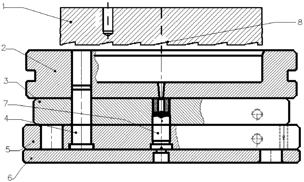
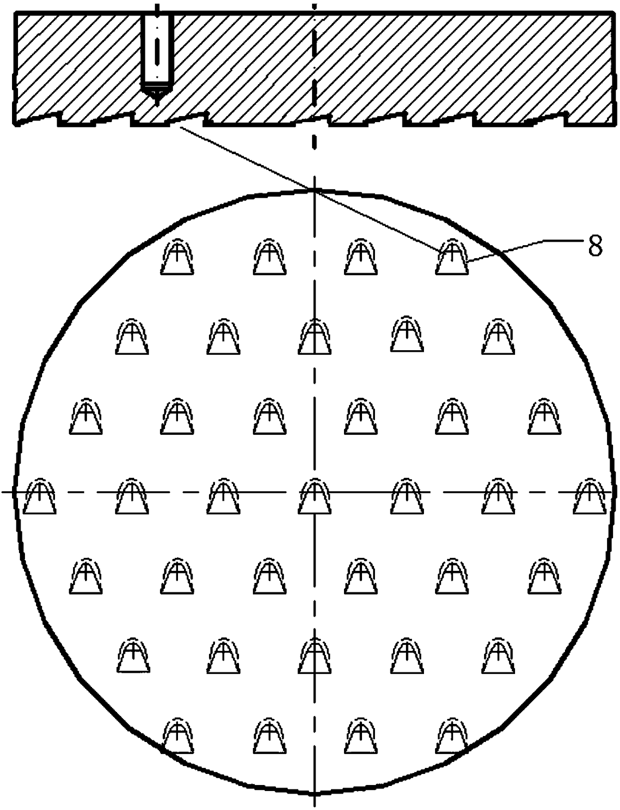
[0016] Such as Figure 1-2 Shown is a compression mold with an automatic feeding structure. The compression mold includes a lower template 5, a middle template 3, a material chamber 2, and a plunger 1 from bottom to top. The guide device 4 guides the lower template 5 , middle template 3, material chamber 2 positions; the bottom of the plunger 1 is provided with a belt structure, the belt structure 8 is a notch, and the vertical position of the top of the notch and the bottom are staggered; the bottom of the lower template 5 A backing plate 6 is provided; the guide device 4 is one of a guide plate, a conduit, and a guide post; the cross-section of the strip structure is obtuse-angled triangle, and the obtuse angle is arranged at the bottom.

[0017] When in use, put the preheated plastic into the material chamber 2, the plastic is heated and plasticized into a melt, the plunger 1 descends, presses down on the melt, and the melt squeezes into the mold of the middle template 3 an...


PUM

PropertyMeasurementUnit
thicknessaaaaaaaaaa

Abstract

The invention discloses a compression mold with an automatic charging structure. The compression mold comprises a lower template, a middle template, a material chamber and a plunger in sequence from bottom to top, wherein a guide device is used for guiding rightly the positions of the lower template, the middle template and the material chamber; the bottom of the plunger is provided with the charging structure; the charging structure is a notch; the vertical positions of the top and the bottom of the notch are arranged in a staggered way. The compression mold with the charging structure is simple in structure, the bottom of the plunger is provided with the charging structure, the charging structure is the notch, the vertical positions of the top and the bottom of the notch are arranged ina staggered way. In a compression process, the charging structure notch is filled with melt in the material chamber. After the melt is cured and molded in a crosslinking manner, the plunger is liftedupwards. The vertical positions of the top and the bottom are arranged in a staggered way to form a buckling structure. When the plunger is lifted upwards, the material is lifted simultaneously, so that the steps of taking materials are simplified, and the time and the labor force are saved.

Description

technical field [0001] The invention relates to a compression molding mold provided with a belt material mechanism. Background technique [0002] Compression mold cnrnpressian mold for plastira is referred to as compression mold; it is to add plastic raw materials directly into the open mold cavity, close the mold, and the plastic becomes a fluid state under the action of heat and pressure and fills the cavity, and then chemically crosslinks Or physical cooling to harden and shape the product. The mold used in this method is a compression mold, which is mostly used for thermosetting plastic molding, and can also be used for thermoplastic molding. However, there are currently two ways to take out the plastic waste in the existing compression mold: one is to take out the material chamber from the mold frame, push it into the special equipment, and use the equipment to eject the material; the other is to use a special The ejector plate is pushed into the mold base, and the pr...

Claims


Application Information

Patent Timeline
Patent Type & Authority Applications(China)
IPC IPC(8): B29C43/36B29C43/50
CPCB29C43/36B29C43/50B29C2043/503
Inventor 杨积锡
Owner 南京华腾汽配有限公司
Features
  • R&D
  • Intellectual Property
  • Life Sciences
  • Materials
  • Tech Scout
  • Unparalleled Data Quality
  • Higher Quality Content
  • 60% Fewer Hallucinations
Learn More