
Single steel wheel front axle and its road roller

A front axle and road roller technology, applied in the directions of roads, roads, axles, etc., can solve the problems of large turning range of road rollers, unfavorable work efficiency, difficulty in adjustment, etc., achieve adjustable compaction weight, increase the scope of application, and improve work efficiency Effect

Active Publication Date: 2020-02-11
CHONGQING UNIV OF ARTS & SCI
View PDF6 Cites 0 Cited by
  • Summary
  • Abstract
  • Description
  • Claims
  • Application Information

AI Technical Summary

Problems solved by technology

With the gravity of the machine itself, the road roller is suitable for various compaction operations, so that the layer to be rolled can be permanently deformed and compacted; while the existing road rollers often need to compact large areas of flat land during on-site construction. When working, the driver needs to make a large turn and turn around when compacting a row of land, and then adjust the direction to continue compacting close to the adjacent compacted land; and due to the existence of steel wheels, the road roller turns relatively large, It is difficult to adjust the direction after turning around, which is not conducive to the improvement of work efficiency

Method used


Image

  • Single steel wheel front axle and its road roller
  • Single steel wheel front axle and its road roller

Examples


Embodiment Construction

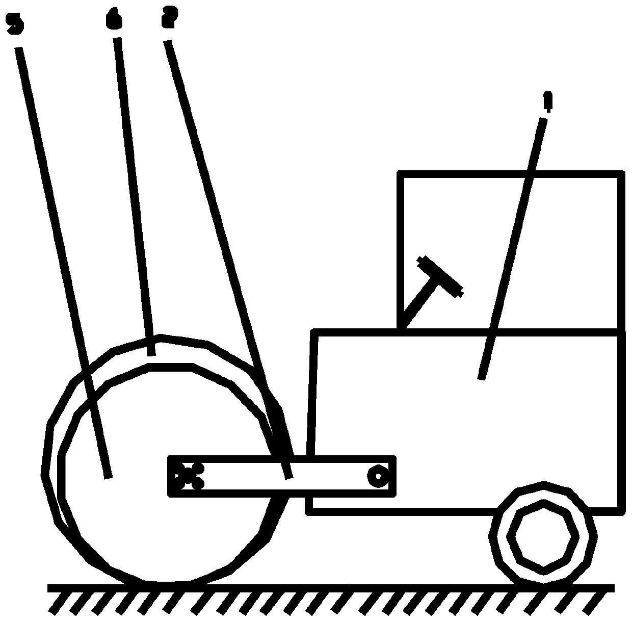
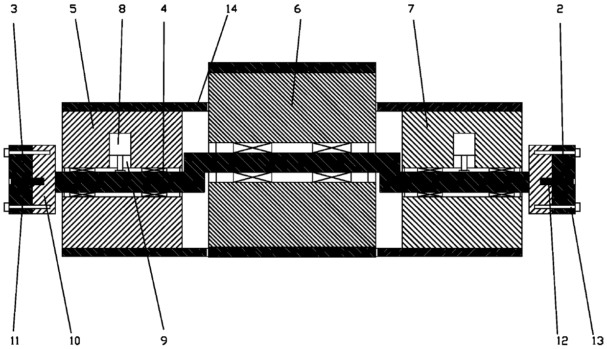
[0015] figure 1 It is a structural schematic diagram of the present invention, figure 2 It is a schematic structural view of the drum in the present invention. As shown in the figure, the road roller in the present embodiment includes a car body 1, a steel cylinder for road compaction, a roller front axle connected to the steel cylinder and the front end of the car body, and is provided with The rear tire assembly on the rear side of the car body; the rear tire assembly is an existing rear wheel mechanism that can be controlled to steer, and will not be described in detail here; the front axle of the roller press includes a left longitudinal beam 2 and a right longitudinal beam 3 And the beam 4, the rear end of the left longitudinal beam and the rear end of the right longitudinal beam are hinged to the front end of the car body, and the transverse beam is fixed between the front ends of the left and right longitudinal beams in the transverse direction; the transverse beam pen...


PUM


Abstract

The invention discloses a single steel wheel front axle and a road roller. The road roller comprises a vehicle body, a steel cylinder, a road roller front axle and a rear tire assembly, wherein the steel cylinder is used for rolling a road; the road roller front axle is connected to the steel cylinder and the front end of the vehicle body; the rear tire assembly is arranged on the rear side of thevehicle body; the road roller front axle comprises a left longitudinal beam, a right longitudinal beam and a cross beam; the rear end of the left longitudinal beam and the rear end of the right longitudinal beam are both hinged at the front end of the vehicle body; the cross beam is fixed between the two front ends of the left longitudinal beam and the right longitudinal beam in the transverse direction; the cross beam runs through the steel cylinder in the transverse direction and pushes the steel cylinder to roll forwards; the steel cylinder comprises a first steel cylinder, a second steelcylinder and a third steel cylinder which are arranged in parallel in the transverse direction; the first steel cylinder, the second steel cylinder and the third steel cylinder independently and rotationally sleeve the cross beam; a first locking device and a third locking device correspondingly used for circumferentially locking rotations of the first steel cylinder and the third steel cylinder are correspondingly arranged in the first steel cylinder and the second steel cylinder; and the lowest points of the first steel cylinder, the second steel cylinder and the third steel cylinder are collinear.

Description

technical field [0001] The invention relates to the technical field of construction machinery road rollers, in particular to a single steel wheel front axle and a road roller thereof. Background technique [0002] The road roller, also known as the soil compactor, is a kind of equipment for road construction. Road rollers belong to the category of road equipment in construction machinery. They are widely used in the filling and compaction operations of large-scale engineering projects such as high-grade highways, railways, airport runways, dams, and stadiums. They can roll sandy, semi-cohesive and cohesive soils, Subgrade stabilized soil and asphalt concrete pavement layer. With the gravity of the machine itself, the road roller is suitable for various compaction operations, so that the layer to be rolled can be permanently deformed and compacted; while the existing road rollers often need to compact large areas of flat land during on-site construction. When working, the d...

Claims


Application Information

Patent Timeline
Patent Type & Authority Patents(China)
IPC IPC(8): B60B35/00B62D15/00E01C19/26
CPCB60B35/00B62D15/00E01C19/26
Inventor 罗天洪刘辉付强
Owner CHONGQING UNIV OF ARTS & SCI
Learn More