Lifting appliance for production

A technology of a spreader and a fixed seat, which is applied in the directions of load hanging components, transportation and packaging, can solve the problems of difficulty in ensuring the closure of the spreader, wire rope breakage, dangerous accidents, etc., saving process time, reducing labor intensity, high precision effect

Inactive Publication Date: 2018-11-16
ANHUI YUTE CONCRETE STRUCTURE TECH
View PDF0 Cites 0 Cited by
  • Summary
  • Abstract
  • Description
  • Claims
  • Application Information

AI Technical Summary

Problems solved by technology

Although this kind of hook or claw can fix the object to be transported, the current spreader uses a wire rope to control the movement of the spreader, and it is easy to cause the wire rope to break due to long-term wear and tear, resulting in dangerous accidents.
Moreover, during the transfer process, it is difficult to ensure the closure of the spreader

Method used


Image

  • Lifting appliance for production
  • Lifting appliance for production
  • Lifting appliance for production

Examples


Embodiment Construction

[0014] The preferred implementation of the production hanger of the present invention will be described in detail below in conjunction with the accompanying drawings.

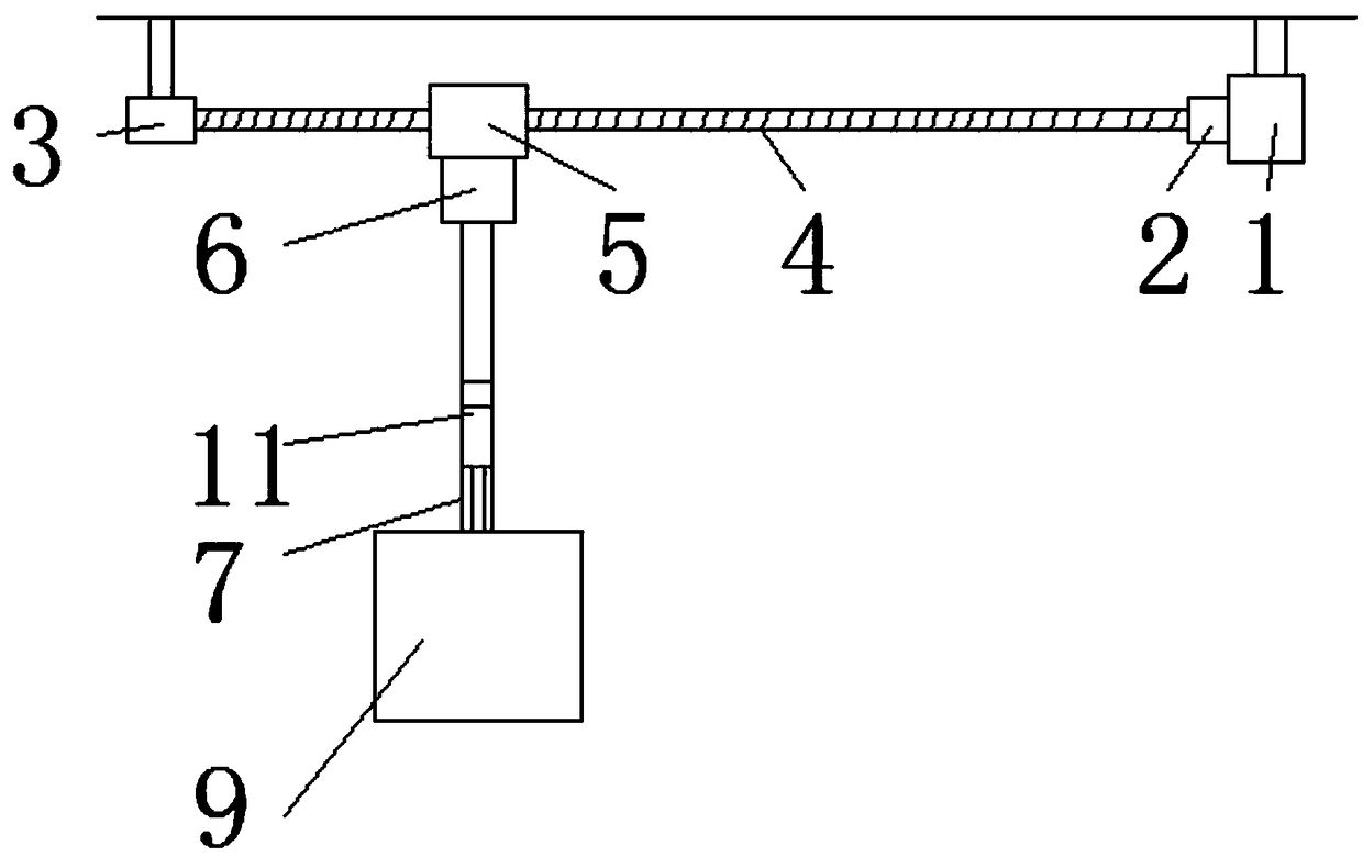
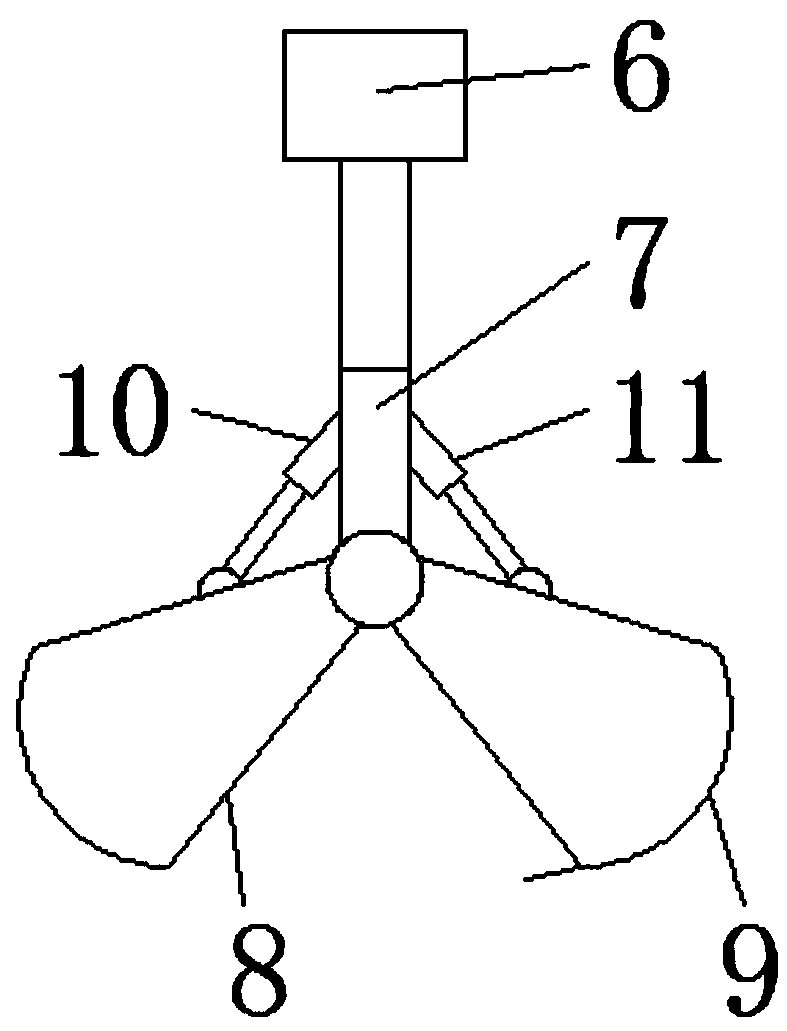
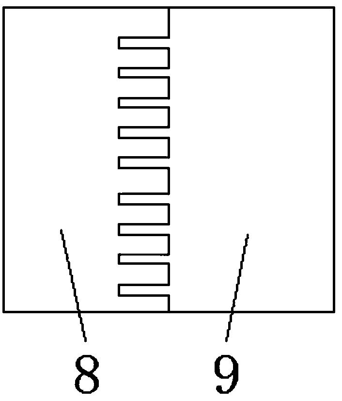
[0015] Figure 1-Figure 3 Show the specific implementation of the production sling of the present invention: a production sling, including a fixed seat 1, the fixed seat 1 is provided with a motor 2, the main shaft of the motor 2 is connected with a lead screw 4 through a coupling , the other end of the lead screw 4 is rotatably connected with a swivel seat 3, the lead screw 4 is also provided with a lead screw nut 5 threaded with the lead screw 4, and the lower end of the lead screw nut 5 is fixed with a hydraulic drive mechanism 6, so The end of the piston cylinder of the hydraulic drive mechanism 6 is connected with a bracket 7, and the bottom end of the bracket 7 is hinged with a symmetrically arranged left grab bucket 8 and a right grab bucket 9, and the left and right sides of the bracket 7 are also hinge...


PUM


Abstract

The invention discloses a lifting appliance for production, and relates to the field of transportation devices. The lifting appliance comprises a fixed seat, wherein a motor is arranged on the fixed seat, a main shaft of the motor is connected with a lead screw through a coupling, the other end of the lead screw is rotationally connected with a rotating seat, and a lead screw nut which is in threaded fit with the lead screw is further arranged on the lead screw; and a hydraulic driving mechanism is fixed at the lower end of the lead screw nut, the end part of a piston cylinder of the hydraulicdriving mechanism is connected with a support, a left grab bucket and a right grab bucket which are symmetrically arranged are hinged to the bottom end of the support, and a left hydraulic cylinder and a right hydraulic cylinder are hinged to the left side and the right side of the support respectively. According to the lifting appliance, the end parts of the piston cylinders of the left hydraulic cylinder and the right hydraulic cylinder are hinged to the left grab bucket and the right grab bucket on the corresponding sides respectively so that the transfer work of an injection molding partcan be realized, and the injection molding part is moved to equipment such as a feeding device of the next procedure; and the grab buckets are simple in structure, the height and the left and right positions can be adjusted, moreover, the control is more accurate, the precision is high, the working procedure time is saved, and the labor intensity is reduced.

Description

technical field [0001] The invention relates to the field of transportation devices, in particular to a production sling. Background technique [0002] Spreaders are widely used in industrial production, such as driving and cranes. During the use of these spreaders, it is necessary to first fix the object to be transported on the hook or claw of the spreader, and then carry it. The existing hooks or claws of the spreader are generally arranged on the connecting rod, and the object to be transported is fixed between at least two hooks or claws. Although this kind of hook or claw can fix the object to be transported, the current spreader utilizes a steel wire rope to control the action of the spreader, which is prone to breakage of the steel wire rope due to long-term wear and tear, resulting in dangerous accidents. Moreover, in the process of transfer, it is difficult to ensure the closure of the spreader. Contents of the invention [0003] The technical problem to be sol...

Claims


Application Information

Patent Timeline
IPC IPC(8): B66C3/16B66C3/02
CPCB66C3/16B66C3/02
Inventor 李明贤
Owner ANHUI YUTE CONCRETE STRUCTURE TECH
Why Eureka
Try Eureka