Supercharge Your Innovation With Domain-Expert AI Agents!

Continuously variable transmission used for forklift

A variable-speed transmission and forklift technology, which is applied in transmission devices, fluid transmission devices, belts/chains/gears, etc., can solve the problems of difficult starting and shifting operations, high energy consumption, and low transmission efficiency of torque converters.

Pending Publication Date: 2018-11-16
福建华南重工机械制造有限公司
View PDF0 Cites 2 Cited by
  • Summary
  • Abstract
  • Description
  • Claims
  • Application Information

AI Technical Summary

Problems solved by technology

[0006] The mechanical transmission gearbox has the advantages of the highest transmission efficiency and low cost; but it has small starting torque, difficult starting and shifting operations, and poor comfort, so it is only used in small-tonnage low-end forklifts
[0007] Hydraulic transmission has large starting torque, easy operation, and moderate cost. It is the most widely used technology in the market at present; however, due to the very low transmission efficiency of the torque converter during starting and acceleration, the energy consumption is the largest among several transmission modes. It is especially prominent on forklifts that need to start and accelerate frequently
[0008] Hydrostatic transmission has large starting torque, stable acceleration, easy and precise operation, continuously variable speed ratio, the best comfort, and transmission efficiency between hydraulic transmission and mechanical transmission, but the cost is the highest among several transmission methods, especially Especially in large-tonnage forklifts, due to the need to take into account low-speed, high-torque traction and high-speed driving requirements, high-power pumps and motors are required, and the cost problem is more prominent.

Method used


Image

  • Continuously variable transmission used for forklift
  • Continuously variable transmission used for forklift
  • Continuously variable transmission used for forklift

Examples


Embodiment Construction

[0023] In order to further explain the technical solution of the present invention, it will be described in detail below in conjunction with the accompanying drawings.

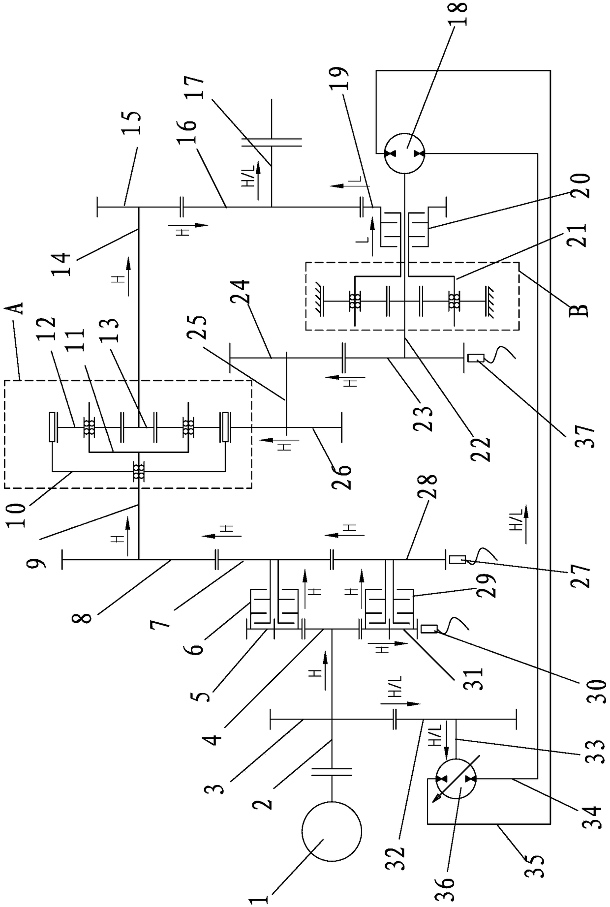
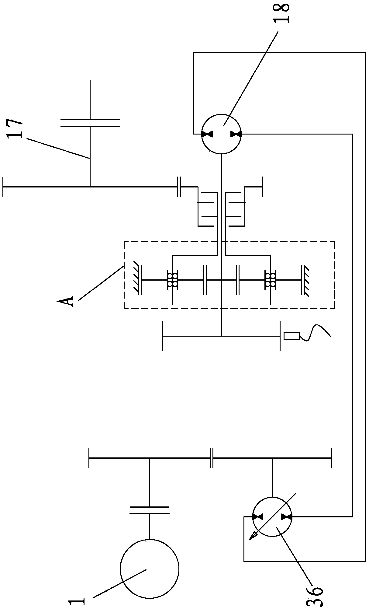
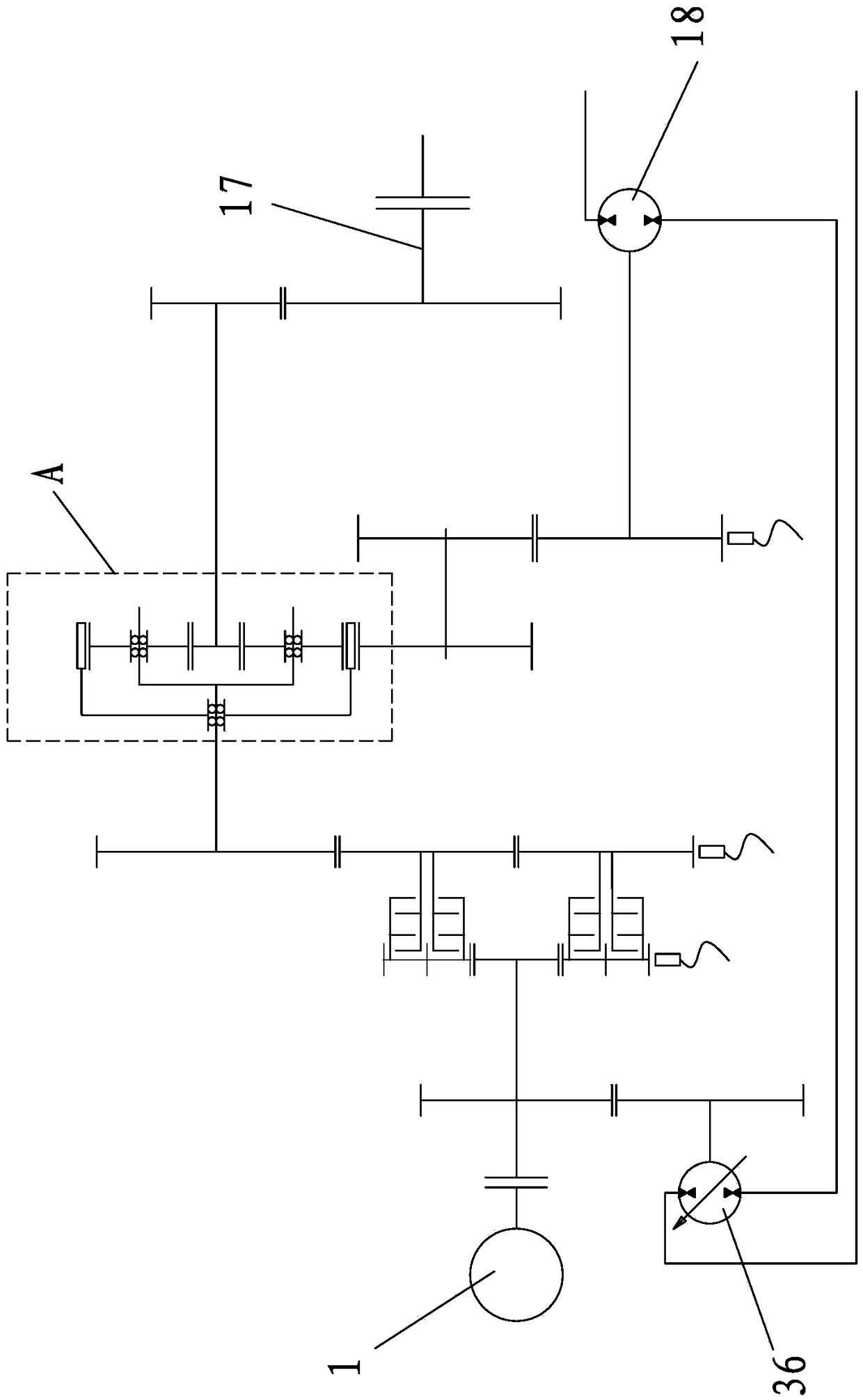
[0024] refer to Figure 1 to Figure 6 , a continuously variable transmission device for a forklift, characterized in that it includes an engine 1, a first gear 3 connected to the output shaft of the engine 1, a second gear 32 meshed with the first gear 3, and an output shaft of the engine 1 The third gear 4 in drive connection, the fourth gear 5 meshing with the third gear 4, the fifth gear 31 meshing with the third gear 4, the sixth gear 7, the seventh gear 28, the eighth gear 8, and the planetary gear mechanism A. The ninth gear 15, the tenth gear 16, the eleventh gear 19, the twelfth gear 23, the first hydraulic pump / motor 36 and the second hydraulic pump / motor 18, the first hydraulic pump / motor 36 and the second hydraulic pump / motor The hydraulic pump / motor 18 communicates with the second oil pipe 35 thro...


PUM


Abstract

The invention relates to a continuously variable transmission used for a forklift. The continuously variable transmission comprises an engine, a first gear, a second gear, a third gear, a fourth gear,a fifth gear, a sixth gear, a seventh gear, an eighth gear, a planet gear mechanism A, a ninth gear, a tenth gear, an eleventh gear, a twelfth gear, a first hydraulic pump / motor and a second hydraulic pump / motor. The second gear is in transmission connection with a transmission shaft of the first hydraulic pump / motor. The twelfth gear is connected with the second hydraulic pump / motor through a first transmission shaft. The fourth gear is in transmission connection with the sixth gear through a first clutch. The fifth gear is in transmission connection with the seventh gear through a second clutch. The eighth gear is connected to a planet gear carrier of the planet gear mechanism A through a second transmission shaft. A gear ring of the planet gear mechanism A is in transmission connectionwith the twelfth gear. A sun gear of the planet gear mechanism A is in transmission connection with the ninth gear through a third transmission shaft. The continuously variable transmission has the beneficial effects of being high in transmission efficiency, stable in operation and low in cost.

Description

technical field [0001] The invention relates to a continuously variable transmission device for a forklift, which belongs to the technical field of forklifts. Background technique [0002] The driving conditions of forklifts are complex, requiring frequent starting, shifting, stopping, and reversing. The performance of the forklift transmission system determines the starting / accelerating ability, operating stability, comfort, energy consumption and other important indicators to measure the performance of forklifts. At present, there are three mainstream transmission technologies for internal combustion forklifts, namely mechanical transmission, hydraulic transmission, and hydrostatic transmission. The transmission routes are as follows: [0003] Mechanical transmission: engine→multi-speed gear transmission controlled by clutch or synchronizer→drive axle. [0004] Hydraulic transmission: engine→hydraulic torque converter→single-speed reducer or multi-speed gear transmission→...

Claims


Application Information

Patent Timeline
IPC IPC(8): F16H47/04F16H47/08
CPCF16H47/04F16H47/08
Inventor 庄钦河庄伟永万禹平郭俊锋张墨郭海波郭潇鹏庄燊燊郭炎波郭俊阳曾忠晏龙水池
Owner 福建华南重工机械制造有限公司
Features
  • R&D
  • Intellectual Property
  • Life Sciences
  • Materials
  • Tech Scout
  • Unparalleled Data Quality
  • Higher Quality Content
  • 60% Fewer Hallucinations
Learn More