
Double-base MIMO radar angle measurement optimization method based on beam space

An optimization method and bistatic technology, applied in radio wave measurement systems, radio wave reflection/reradiation, measurement devices, etc., can solve the problem that the main lobe width and side lobe level cannot be effectively controlled, and the ratio of main lobe and side lobe low level problem

Active Publication Date: 2018-11-16
XIDIAN UNIV
View PDF8 Cites 6 Cited by
  • Summary
  • Abstract
  • Description
  • Claims
  • Application Information

AI Technical Summary

Problems solved by technology

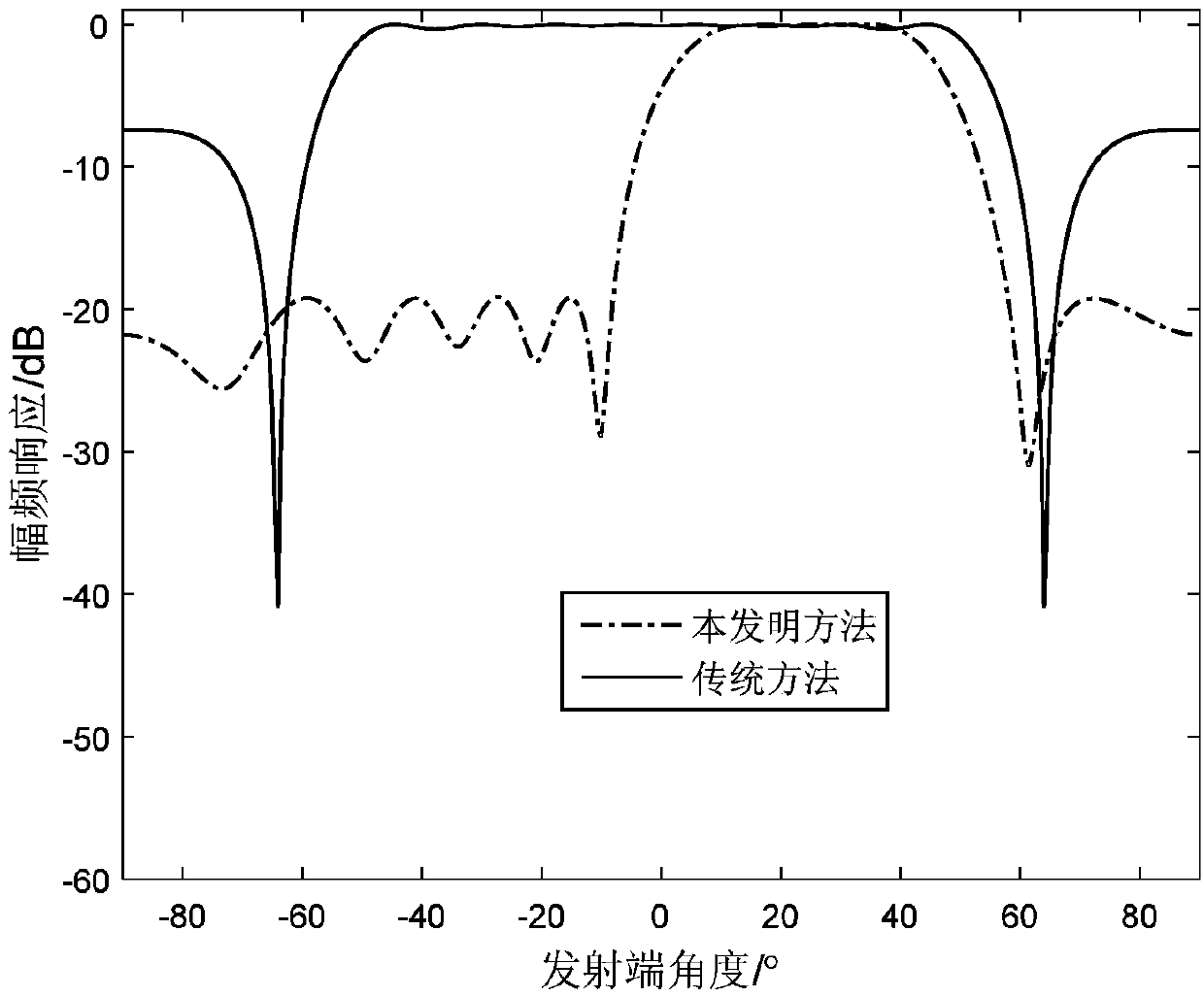
[0008] The document "Beamspace ESPRIT algorithm for bistatic MIMO radar" introduces a beam-domain-based ESPRIT algorithm. This beam-domain-based ESPRIT algorithm uses a Fourier transform matrix to convert the received signal from the element domain to the beam domain to achieve improved The purpose of angle measurement accuracy; however, because the spatial domain filter it uses is composed of several Fourier transform beams, its main lobe width and side lobe level cannot be effectively controlled, resulting in a low main-side lobe ratio. This is a significant shortcoming of the traditional beam-domain ESPRIT angle measurement method

Method used


Image

  • Double-base MIMO radar angle measurement optimization method based on beam space
  • Double-base MIMO radar angle measurement optimization method based on beam space
  • Double-base MIMO radar angle measurement optimization method based on beam space

Examples


specific Embodiment approach

[0069] Step 3, use The transmit beam matrix W e and The receiving beam matrix W r , perform spatial filtering on the signal matrix Z of Q pulses after matched filtering, convert the echo signal model from the element domain to the beam domain, and obtain a signal model based on the beam domain The specific implementation is as follows:

[0070]

[0071] in, represents the Kronecker product.

[0072] Substitute the expression of the signal matrix Z of Q pulses after matched filtering into the above formula to get

[0073]

[0074] in, Note here that if there is no interpolation error, there is an equality relationship and matrix and There are the following forms:

[0075]

[0076]

[0077] in,

[0078] Under this premise, the above formula can be converted into an optimized signal model:

[0079]

[0080] Among them, ⊙ represents the Khatri-Rao product, Z represents the signal matrix of Q pulses after matched filtering, and C represents th...


PUM


Abstract

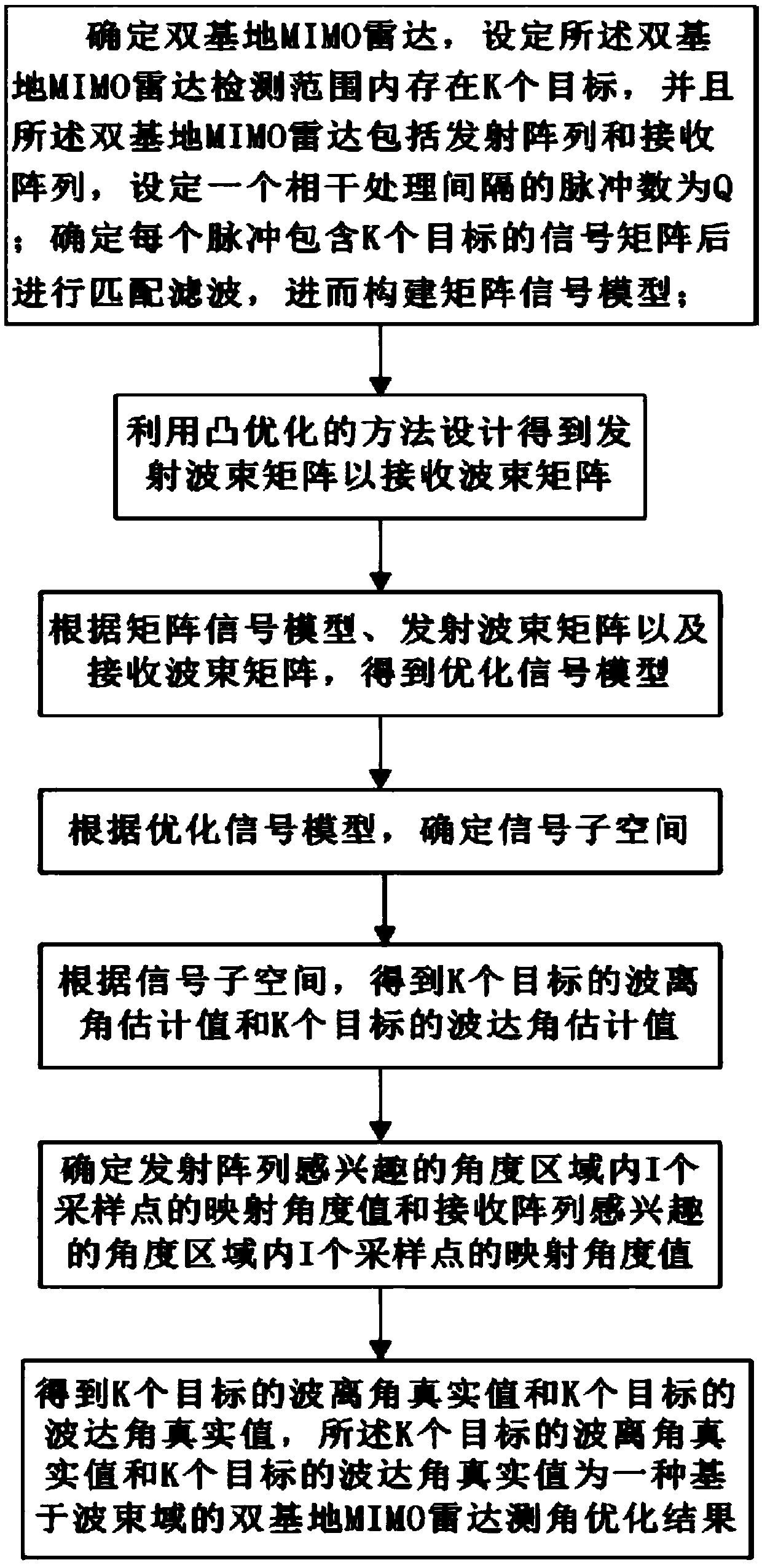
The invention discloses a double-base MIMO radar angle measurement optimization method based on a beam space. The method comprises the steps of determining a double-base MIMO radar, setting a fact that K targets exist in the detecting range of the double-base MIMO radar, and setting the number of pulses in a coherent processing interval to Q; after determining a fact that each pulse comprises thesignal matrix of the K targets, performing matched filtering, and furthermore performing a matrix signal model; designing by means of a convex optimization method for obtaining a transmitting beam matrix and receiving a beam matrix and optimizing the signal model; determining a signal sub-space, obtaining wave departure angle estimated values and wave arrival angle estimated values of the K targets; determining mapping angle values of I sampling points in an angle area thetae which is interested by a transmitting array and mapping angle values of the I sampling points in an angle area thetar which is interested by a receiving array; further obtaining the wave departure angle true values and the wave arrival angle true values of the K targets, thereby obtaining a double-base MIMO radar angle measurement optimization result based on the beam space.

Description

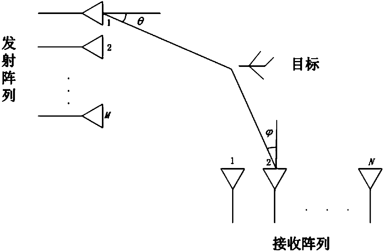
technical field [0001] The invention belongs to the technical field of radar parameter estimation, in particular to an angle measurement optimization method for a bistatic MIMO radar based on a beam domain, which is applicable to the estimation of the wave departure angle and the wave arrival angle in the bistatic MIMO radar. Background technique [0002] MIMO radar is a new system radar proposed in recent years. It draws lessons from the multiple-input multiple-output technology that has been widely used in the communication field, and has some unique advantages. [0003] MIMO radar can be divided into two categories: statistical MIMO radar and centralized MIMO radar. Statistical MIMO radar antenna array has a large interval between elements. Using space diversity technology, the transmitted signals of each transmitting element are not correlated. Using Space diversity and transmit diversity technologies form multiple channels, which greatly reduces the impact of radar refl...

Claims


Application Information

Patent Timeline
IPC IPC(8): G01S13/68G01S13/00G01S7/41
CPCG01S7/411G01S7/418G01S13/003G01S13/68
Inventor 赵永波徐保庆何学辉刘宏伟苏洪涛苏涛
Owner XIDIAN UNIV
Learn More