Display device

A technology for a display device and a display area, which is applied in nonlinear optics, instruments, optics, etc., can solve problems such as light leakage at the edge of the hole-digging area, and achieve the effects of solving edge light leakage, avoiding edge light leakage, and reducing light intensity

Active Publication Date: 2018-11-16
XIAMEN TIANMA MICRO ELECTRONICS
View PDF5 Cites 14 Cited by
  • Summary
  • Abstract
  • Description
  • Claims
  • Application Information

AI Technical Summary

Problems solved by technology

[0003] Usually, a non-display area is set within the range of the display area of ​​the display device, and a hole-digging area is set in the non-display area, which easily leads to light leakage at the edge of the hole-digging area.

Method used


Image

  • Display device
  • Display device
  • Display device

Examples


Embodiment Construction

[0022] The present invention will be further described in detail below in conjunction with the accompanying drawings and embodiments. It should be understood that the specific embodiments described here are only used to explain the present invention, but not to limit the present invention. In addition, it should be noted that, for the convenience of description, only some structures related to the present invention are shown in the drawings but not all structures.

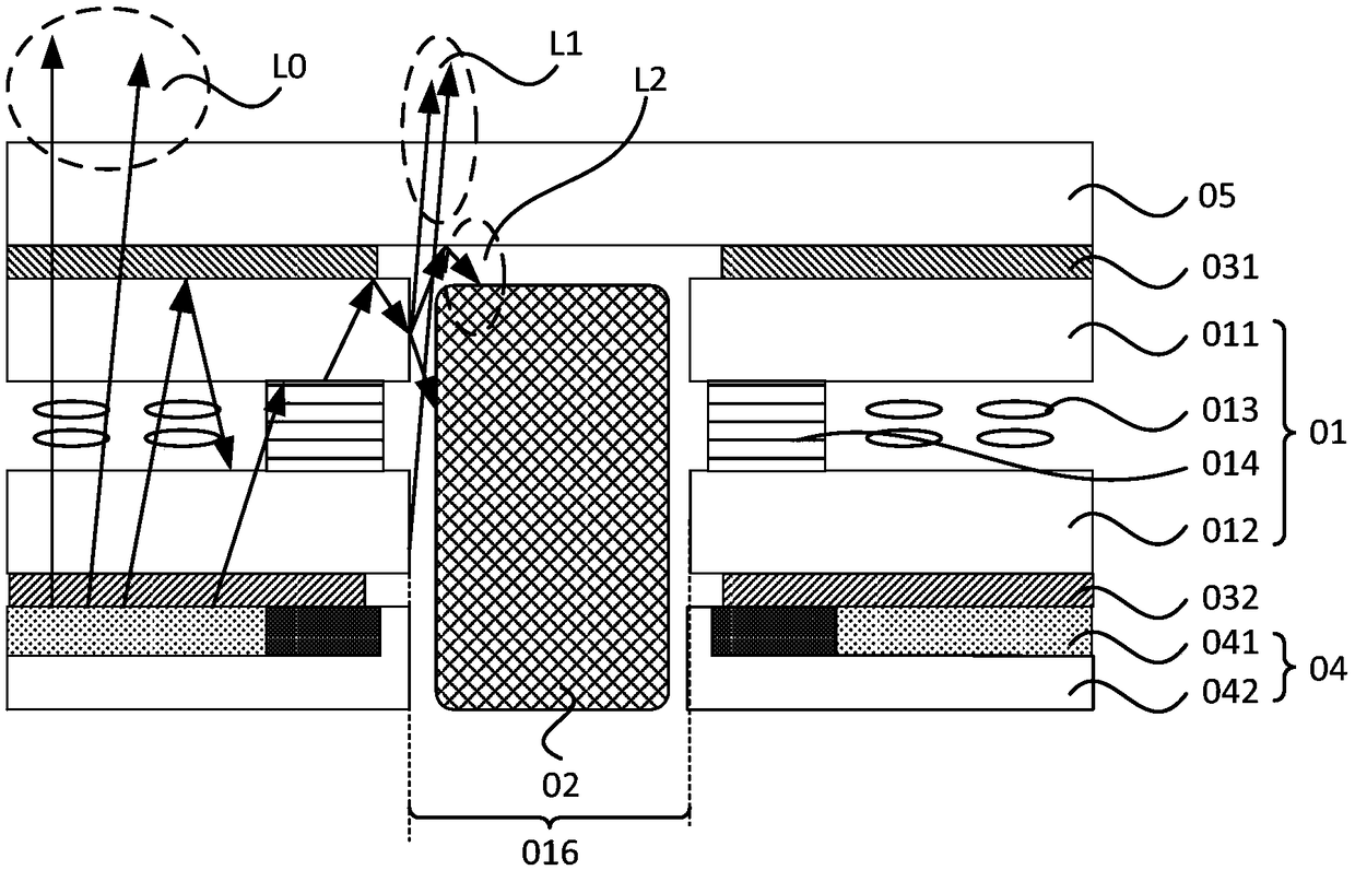
[0023] figure 1 A schematic structural diagram of a display device provided in the prior art. refer to figure 1 , taking a liquid crystal display device as an example for illustration, the display device includes a display panel 01 , a photosensitive module 02 , a backlight module 04 , an upper polarizer 031 , a lower polarizer 032 and a cover 05 . Wherein, the display area of ​​the display device is punched, that is, the punched area 016 is set at the positions corresponding to the display panel 01, the upper p...


PUM

PropertyMeasurementUnit
thicknessaaaaaaaaaa

Abstract

The embodiment of the invention discloses a display device. The display device comprises a display panel and a functional module. The display panel comprises a first substrate, the first substrate islocated on the light outlet side of the display panel and comprises a display zone and at least one first via hole, and the display zone surrounds the first via holes. The first substrate comprises afirst surface and a second surface opposite to the first surface, the first surface is the surface close to the light outlet side of the display panel, the opening area of the first via holes on the first surface is smaller than that of the first via holes on the second surface, an included acute angle formed by the inner side wall of the first via holes and the first surface is alpha and is greater than or equal to 30 degrees but is smaller than 90 degrees, and the functional module is located below orthographic projections of the first via holes on the first surface. The display device can make light emitted from the edges of the first via holes offset in the direction of deviating from the light outlet side of the display panel, and accordingly the intensity of light pointing to the light outlet side of the display panel can be reduced, namely light leakage on the edges of the first via holes is decreased.

Description

technical field [0001] The present invention relates to display technology, in particular to a display device. Background technique [0002] With the development of display technology, in order to improve user experience, high screen-to-body ratio has gradually become an important development direction of display devices. The screen-to-body ratio can be understood as the ratio of the viewing area of ​​a display device to the total area of ​​the plane on which it is located. In order to increase the screen-to-body ratio, it is necessary to reduce the area occupied by the frame area of ​​the display device, thereby reducing the area occupied by the non-display area. For this, a non-display area can be set within the range surrounded by the display area, and A hole-digging area is set in the area, which is used to set the modules originally set in the border area (for example: the front camera, front flash, earpiece, etc. on the mobile phone) in the hole-digging area. [0003...

Claims


Application Information

Patent Timeline
Patent Type & Authority Applications(China)
IPC IPC(8): G02F1/1333G02F1/1335
CPCG02F1/1333G02F1/133512
Inventor 刘博智陈国照
Owner XIAMEN TIANMA MICRO ELECTRONICS
Why Eureka
Try Eureka