Side-in backlight module and LCD display device

A side-type backlight and module technology, which is applied in the field of liquid crystal display, can solve the problems of thick direct-type backlight module, poor effect, and difficulty in side-light partition control, so as to facilitate the development of light and thin and improve high dynamic contrast ratio Effect

Inactive Publication Date: 2018-11-16
TCL CHINA STAR OPTOELECTRONICS TECH CO LTD
View PDF5 Cites 12 Cited by
  • Summary
  • Abstract
  • Description
  • Claims
  • Application Information

AI Technical Summary

Problems solved by technology

[0004] The backlight types of liquid crystal display devices mainly include direct-type backlight and side-type backlight. The direct-type backlight has become the mainstream of the market because the partitions of the LED light source and the partitions of the liquid crystal display panel can be one-to-one corresponding, and the effect of local dimming is good. However, the size of the direct-lit backlight module is relatively thick, which cannot meet the pursuit of ultra-thin liquid crystal display devices in the market
As for the side-type backlight module, since the light source is used to enter the light from the side, and the light guide plate is used as the carrier of light transmission, although it meets the pursuit of ultra-thin liquid crystal displays in the market, it is precisely because the side-type backlight module It is a side light mode, and it is difficult to control its side light partitions, and it is impossible to achieve effective multi-zone control to achieve two-dimensional brightness control, so its HDR effect is poor

Method used


Image

  • Side-in backlight module and LCD display device
  • Side-in backlight module and LCD display device
  • Side-in backlight module and LCD display device

Examples


Embodiment Construction

[0024] In order to make the objectives, technical solutions and advantages of the present invention clearer, the specific embodiments of the present invention will be described in detail below with reference to the accompanying drawings. Examples of these preferred embodiments are illustrated in the accompanying drawings. The embodiments of the invention shown in the drawings and described with reference to the drawings are merely exemplary and the invention is not limited to these embodiments.

[0025] Here, it should also be noted that, in order to avoid obscuring the present invention due to unnecessary details, only the structures and / or processing steps closely related to the solution according to the present invention are shown in the drawings, and the related structures and / or processing steps are omitted. Other details not relevant to the invention.

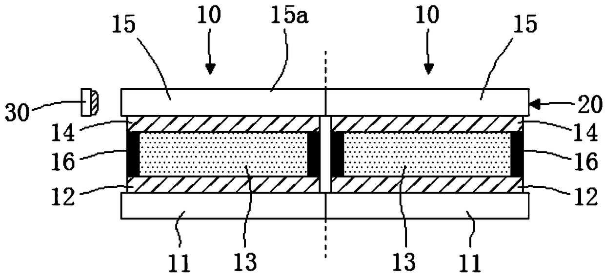
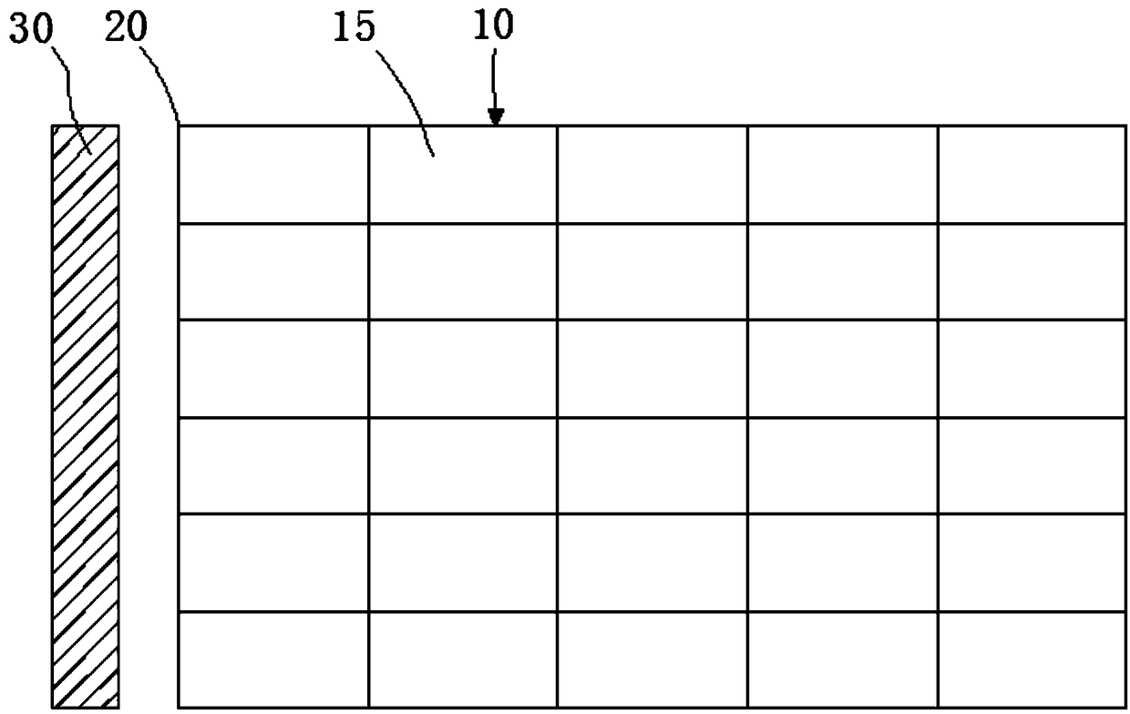
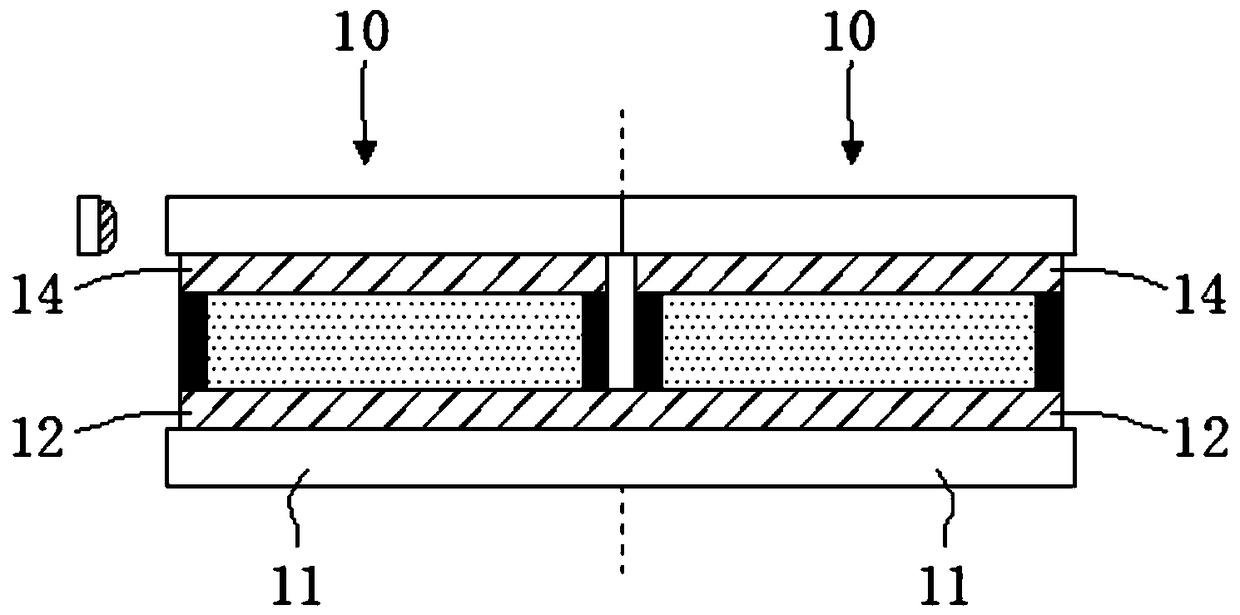
[0026] This embodiment first provides an edge-type backlight module, refer to figure 1 and figure 2 , the edge-type...


PUM


Abstract

The invention discloses a side-in backlight module, which comprises a plurality of light control units which can be independently controlled, wherein the light control unit comprises a first substrate, a first electrode, a polymer liquid crystal layer, a second electrode and second substrates which are sequentially disposed, a side surface of the polymer liquid crystal layer is provided with a light shielding layer, and the first electrode and the second electrode are used to form an electric field applied on the polymer liquid crystal layer to adjust scattering state of light by the polymer liquid crystal layer, wherein at least the second electrode and the second substrate are transparent, and the second substrates of all the light control units are sequentially closely joined to form alight guide plate, and a side surface of the light guide plate is provided with a light source. The invention also discloses a liquid crystal display device comprising the side-in backlight module. The side-in backlight module can realize the partial dimming by using the side-in backlight to realize the partition block control, and realize the effect of high dynamic contrast, and is also beneficial to the thin and light development of the liquid crystal display device.

Description

technical field [0001] The present invention relates to the technical field of liquid crystal display, in particular to an edge-type backlight module, and also to a liquid crystal display device including the edge-type backlight module. Background technique [0002] Among flat panel display devices, Liquid Crystal Display (LCD) has the characteristics of small size, low power consumption, relatively low manufacturing cost and no radiation, and occupies a dominant position in the current flat panel display market. [0003] In recent years, with the development of high dynamic contrast (High-Dynamic Range, HDR) technology, the HDR technology is increasingly applied to liquid crystal display devices. To implement the HDR technology in the liquid crystal display device, special technical requirements are put forward for the backlight unit of the liquid crystal display device, and the backlight unit of the liquid crystal display device should be able to realize sub-block control ...

Claims


Application Information

Patent Timeline
Patent Type & Authority Applications(China)
IPC IPC(8): G02F1/1334G02F1/1343G02F1/13357G02B6/00
CPCG02B6/005G02F1/1334G02F1/133606G02F1/1343G02F1/13345
Inventor 陈黎暄
Owner TCL CHINA STAR OPTOELECTRONICS TECH CO LTD
Why Eureka
Try Eureka