Antenna

An antenna and radio frequency line technology, applied in the direction of antenna grounding switch structure connection, radiation element structure, etc., can solve the problems of difficult to adjust the impedance value, the effect of return loss is not very good, the return loss is large, etc., to achieve shortening The effect of antenna length, wide distribution, and reduced return loss

Inactive Publication Date: 2018-11-16
东莞市森岭智能科技有限公司
View PDF3 Cites 0 Cited by
  • Summary
  • Abstract
  • Description
  • Claims
  • Application Information

AI Technical Summary

Problems solved by technology

[0004] The above-mentioned impedance matching method, because it is difficult to adjust the size of the screw rod to adjust the satisfactory impedance value, so the

Method used


Image

  • Antenna
  • Antenna
  • Antenna

Examples


Embodiment Construction

[0027] The present invention will be described in further detail below in conjunction with the accompanying drawings.

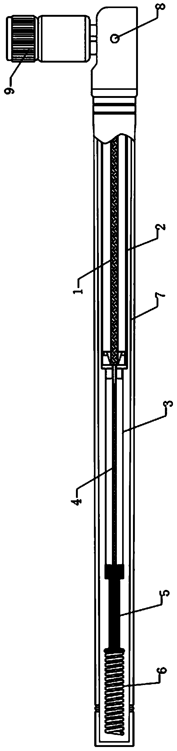
[0028] Such as figure 1 As shown, an antenna includes a radio frequency line 1 , a ground copper tube 2 , a radiation copper tube 3 , a resistance wire 4 , a spiral rod 6 , a rod sleeve 7 and a standard interface 9 .

[0029] The rod sleeve 7 is made of plastic material, and its interior is hollow to form an accommodating cavity 71 .

[0030] from figure 1 Seen from the direction, this kind of antenna is placed horizontally. From the right end to the left end of the accommodating cavity 71 of the rod sleeve 7 there are: radio frequency wire 1, resistance wire 4 and screw rod 6.

[0031] The radio frequency line 1 includes an outer conductor and an inner conductor; the outer conductor is wrapped outside the inner conductor and is insulated from the inner conductor. Specifically, the inner conductor is covered with an inner insulating layer, and the braided o...


PUM


Abstract

The invention discloses an antenna, which belongs to the technical field of antennas. The antenna comprises a radio frequency wire and a screw rod, wherein the radio frequency wire is connected with the screw rod. The antenna also comprises a resistance wire for impedance matching. The radio frequency wire and the screw rod are connected through the resistance wire. The problem of large echo lossof a common rod-sleeve antenna is mainly solved. The antenna performs impedance matching through the resistance wire. In production, a technician selects proper resistance of the resistance wire to carry out impedance matching on the radio frequency wire and the screw rod. As the resistance of the resistance wire is easy to control, in comparison with adjustment on the size of the screw rod, selecting the resistance of the resistance wire can more easily realize impedance matching on the radio frequency wire and the screw rod, and thus, the echo loss of the antenna can be reduced.

Description

technical field [0001] The present invention relates to the technical field of antennas, in particular to an antenna. Background technique [0002] At present, wireless communication technology is developing at a high speed. Wireless communication is inseparable from electromagnetic waves, and antennas are devices that convert guided waves on transmission lines and electromagnetic waves propagating in space. [0003] Antennas in the prior art usually use impedance matching methods to achieve the purpose of reducing the return loss of the antenna. For example, a common pole sleeve antenna encapsulates interconnected radio frequency lines and helical rods in the pole sleeve; the radio frequency line connects the signal The source and the screw rod, the electrical signal of the signal source is transmitted to the screw rod through the radio frequency line, and the screw rod radiates the signal to the space in the form of electromagnetic waves. In the prior art, impedance matchi...

Claims


Application Information

Patent Timeline
IPC IPC(8): H01Q1/50H01Q1/36
CPCH01Q1/36H01Q1/50
Inventor 庄珍彪刘长兴周琨杨凯敏
Owner 东莞市森岭智能科技有限公司
Why Eureka
Try Eureka