Whole optical fiber optical power monitor

An optical power and monitor technology, applied in optical fiber transmission, photometry, optical radiation measurement, etc., can solve the problems of high production cost and low photoelectric detection efficiency, and achieve low production cost, high transmission power processing capability, low The effect of insertion loss

Inactive Publication Date: 2008-12-17
JINAN UNIVERSITY
View PDF5 Cites 11 Cited by
  • Summary
  • Abstract
  • Description
  • Claims
  • Application Information

AI Technical Summary

Problems solved by technology

[0009] The purpose of the present invention is to provide an all-fiber optical power monitor with high photoelectric detection efficiency, simple manufacture and low cost for the existing optical fiber optical power monitors with low photoelectric detection efficiency and high production cost.

Method used


Image

  • Whole optical fiber optical power monitor
  • Whole optical fiber optical power monitor
  • Whole optical fiber optical power monitor

Examples


Embodiment 1

[0031] The manufacturing method of the all-fiber optical power detector of the present invention is as follows:

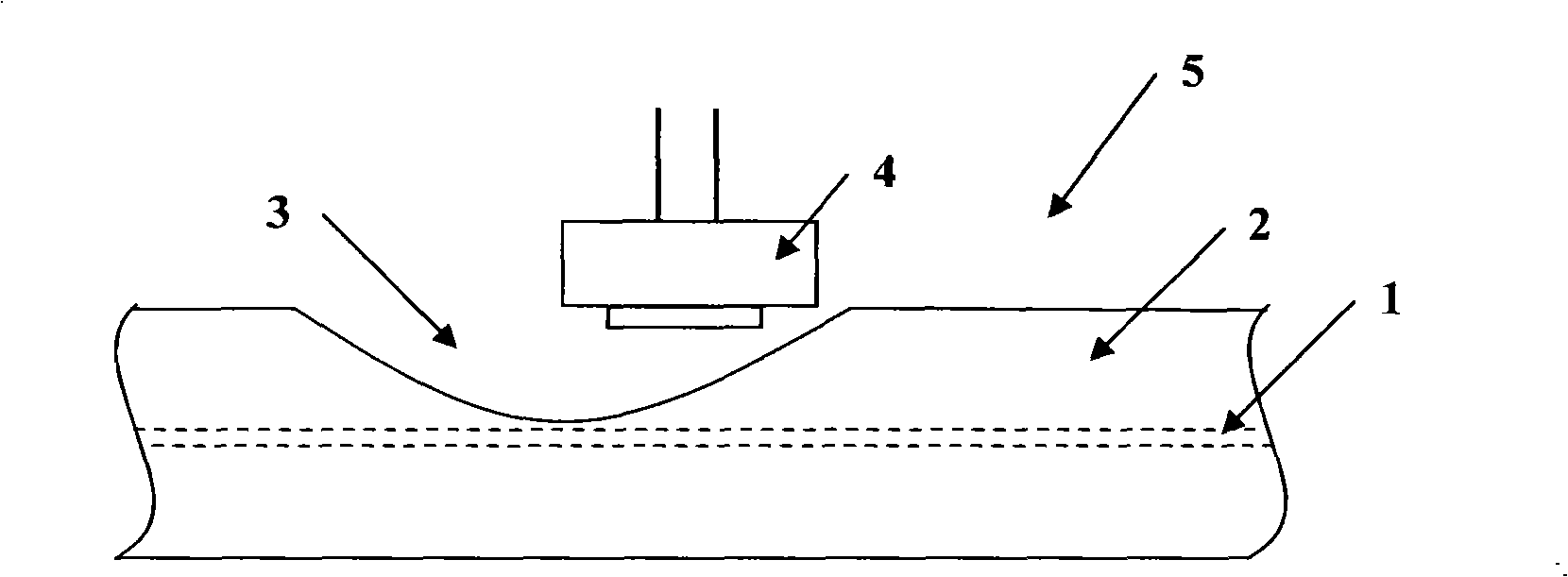
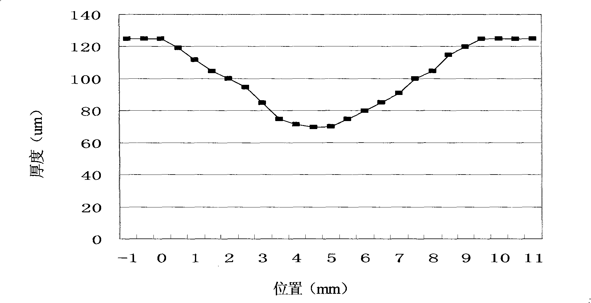
[0032] (1) Use the wheel-type optical fiber side polishing method to perform side polishing on the cladding 2 of a section of optical fiber, and make a section of side polishing area 3 that is V-shaped along the optical fiber axis, as the optical fiber in the fiber core 1 Energy splitting area, the shape of the side polishing area is as image 3 As shown; the distance between the bottom of the V-shaped notch 3 and the fiber core 1 is 3um, and the length of the side polishing area is 9.5mm;

[0033] (2) Stretch the side polished optical fiber 5 and place it straight;

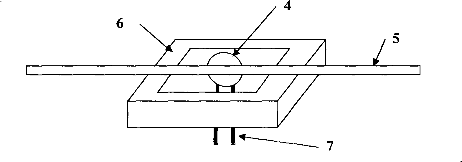
[0034] (3) placing the sensing plane of the photodetector 4 facing the V-shaped notch 3;

[0035] (4) Connect one end of the side-polished optical fiber 5 to the light source, and the other end to the optical power meter, and connect the electrode pin 7 of the photodetector 4 to the digital voltmeter ...

Embodiment 2

[0040] Compared with Example 1, the difference lies in that the distance from the bottom of the V-shaped notch 3 to the fiber core 1 is 5um, and the length of the side polishing area is 5mm.

[0041] Experimental test results show that the insertion loss of the device of this embodiment is 0.35dB, the optoelectric responsivity (optoelectric responsivity) can reach 90mA / W, the polarization-dependent loss is 0.1dB, and the polarization stability (Polarization stability) is 0.3dB.

Embodiment 3

[0043] Polished out Figure 5 The center is the large U-shaped side polishing area. The insertion loss of the side polishing optical fiber is 0.7dB. The same photodetector as in Example 1 is used to detect light energy, and the corresponding photoelectric responsivity is 2.66mA / W. This is because the middle part of the notch is relatively flat, and the flat part of the bottom portion disperses the leaked light energy, which is not conducive to the light energy collection of the photodetector.


PUM


Abstract

The invention discloses a full optical fiber optical power monitor, comprising a photo detector and an optical fiber, characterized in that, the covering of the optical fiber is arranged with a V-shape gap for leaking the light, wherein the minimum distance of the bottom of the V-shape gap is 3-5 mu m away from the surface of the fiber core. The photo detector is arranged on the outside of the V-shape gap, for detecting the leaking light thereof. The invention receives the spectrum energy of the photo detector with high efficiency. The full optical fiber optical power monitor of the invention has low insertion loss, low echo loss and high transmitted power processing ability, which is also applied in the special optical fiber transmission system for the polarization maintaining optical fiber, also is used for manufacturing the full optical fiber apparatuses with small volume and low cost. The full optical fiber optical power monitor of the invention can be used in the high performance optical communication apparatus such as the fiber laser, the optical amplifier, the ultra-narrow light pulse generator and the like, also can be used in the optical fiber sensing field.

Description

technical field [0001] The present invention relates to optical power monitors. Background technique [0002] The rapid development of the telecommunication industry requires the network to be more flexible, reliable, practical, easy to operate and maintain. In optical network applications, the management of each optical path, especially the optical power in the optical fiber, is an important technical content. For example, in an optical fiber amplifier, in order to ensure good detection characteristics of the system, it is usually required that the optical power transmitted in each communication channel be balanced, which leads to a multi-channel optical power equalizer. In addition, at the receiving end of the optical signal pulse, in order to reduce the bit error rate and ensure the consistency of the electrical signal of the system, it is also necessary to manage and control the power of each optical signal. With the development of high-speed optical communication, hig...

Claims


Application Information

Patent Timeline
Patent Type & Authority Applications(China)
IPC IPC(8): H04B10/08G01J1/42H04B10/079H04B10/25
CPCG01J1/4257
Inventor 陈哲张凌童潘昊肖雅婷
Owner JINAN UNIVERSITY
Why Eureka
Try Eureka