A dilator for surgical wounds

A dilator and wound technology, applied in the field of medical devices, can solve the problems of increasing the workload of medical staff, difficulty in controlling the size of the incision, and small surgical field of view, achieving the effects of reducing workload, ingenious structure, and ensuring a hygienic environment

Inactive Publication Date: 2020-07-14
万晶晶
View PDF4 Cites 0 Cited by
  • Summary
  • Abstract
  • Description
  • Claims
  • Application Information

AI Technical Summary

Problems solved by technology

[0005] In view of the above situation, in order to overcome the defects of the prior art, the object of the present invention is to provide a dilator for surgical wounds, which effectively solves the difficulty in controlling the opening size of the incision, the small surgical field of view, time-consuming and laborious work, and increases the workload of medical staff. Burden and other issues

Method used


Image

  • A dilator for surgical wounds
  • A dilator for surgical wounds
  • A dilator for surgical wounds

Examples


Embodiment Construction

[0014] The specific implementation manners of the present invention will be described in further detail below in conjunction with the accompanying drawings.

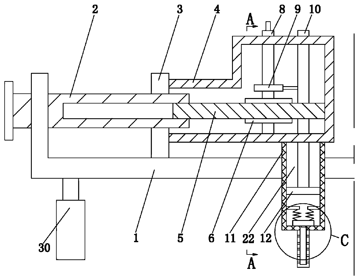
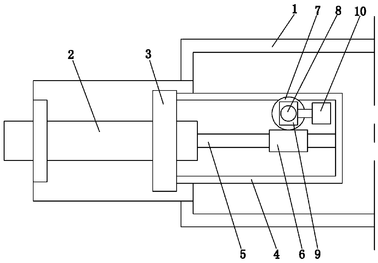
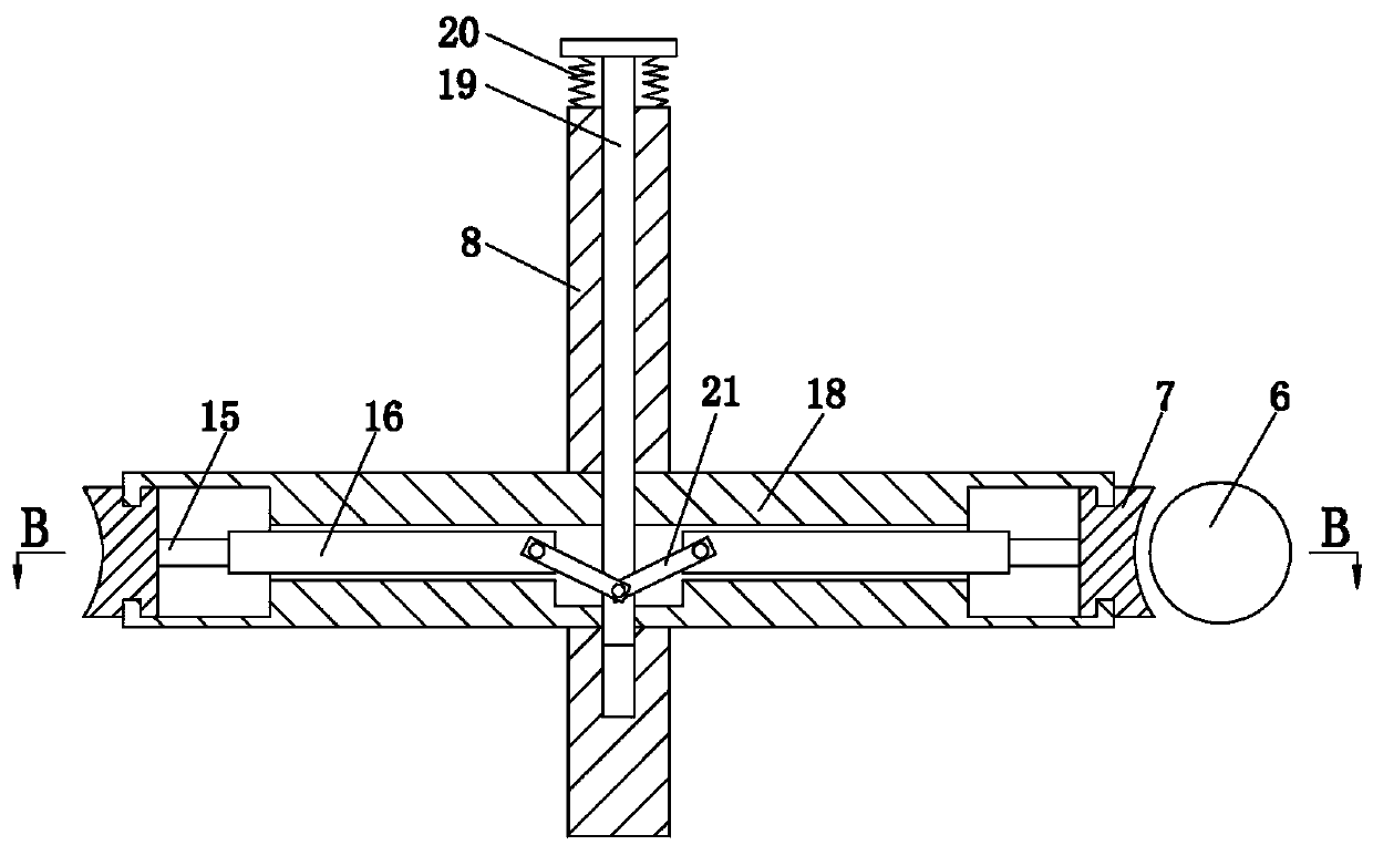
[0015] Depend on Figure 1 to Figure 6 Given, the present invention comprises frame 1, and frame 1 is left and right symmetrically provided with two first lead screws 2, and two first lead screws 2 are rotationally connected with frame 1 respectively, and each first lead screw 2 is threadedly connected with The first nut 3 sliding left and right along the frame 1, the frame 4 is fixed on the side of the first nut 3 away from the end of the frame 1, the first lead screw 2 is spline connected with the drive shaft 5, the drive shaft 5 The other end of the frame body 4 is rotationally connected, and a worm gear mechanism is arranged in the frame body 4. In the described worm gear mechanism, the worm 6 is coaxially fixedly connected with the transmission shaft 5. In the described worm gear mechanism, the worm wheel 7 is coaxi...


PUM


Abstract

The invention discloses an expander for a surgical wound. The problems that the expanding size of an incision is not easy to control, a surgical field is small, and time and labor are wasted are effectively solved. The expander comprises a rack, two first screw rods are symmetrically arranged on the left side and the right side of the rack, and the two first screw rods are rotationally connected with the rack separately; each first lead screw is in threaded connection with a first nut which slides left and right along the rack; a frame body is fixed to the sides, far away from the end of the rack, of the first nuts; each first lead screw is internally connected with transmission shaft through a spline; the frame body is internally provided with a worm and gear mechanism, a worm is coaxially and fixedly connected with the transmission shafts, and a second lead screw is coaxially arranged on a worm wheel; a one-way rotating mechanism is arranged between the second screw rod and the wormwheel, the second screw rod is in threaded connection with a second nut, and the second nut is fixedly provided with a sliding rod which slides up and down along the frame body; a cylinder is fixed atthe lower end of the frame body, and a piston which slides up and down in the cylinder is fixed at the lower end of the sliding rod; a traction plate is fixed at the lower end of the cylinder; a plurality of first through holes communicated with the cylinder are formed in the traction plate.

Description

technical field [0001] The invention relates to the technical field of medical instruments, in particular to a dilator for surgical wounds. Background technique [0002] In the surgical treatment of clinical patients, when medical personnel perform surgical operations on the inside of the human body, they need to cut the patient's surface incision, and then use a medical retractor to pull the incision apart, so that a certain area of ​​vision is formed at the wound, so that the inside of the human body can be seen. Operate the surgical site. At present, the traditional surgical retractors are generally pulled by the hands of medical staff, which is time-consuming and laborious. Sometimes multiple surgical retractors are needed during the operation, which requires multiple people to pull, wasting a lot of manpower. The requirements are small, and when the incision is small, multiple surgical retractors are also needed to pull the incision apart, which is very inconvenient, an...

Claims


Application Information

Patent Timeline
Patent Type & Authority Patents(China)
IPC IPC(8): A61B17/02A61B90/70
CPCA61B17/02A61B90/70
Inventor 万晶晶伍美容成柯兰玲
Owner 万晶晶
Why Eureka
Try Eureka