
Push-and-pull mechanism and electric appliance

A push-pull mechanism and clutch mechanism technology, applied in the field of household appliances, can solve the problems of reducing the reliability and life of the mechanism, reducing the user experience, affecting the gear and rack meshing transmission accuracy and stability, etc., so as to improve the operation reliability and The effect of operating life

Pending Publication Date: 2018-11-20
乔坤
View PDF0 Cites 0 Cited by
  • Summary
  • Abstract
  • Description
  • Claims
  • Application Information

AI Technical Summary

Problems solved by technology

[0004] Although the drum washing machine provided by the prior art can realize the automatic door opening and closing of the washing machine to a certain extent, when the door body is in the closed state, the gear and the rack are in the meshing state. At this time, if the user wants to manually open the door body, then Since the gear and the rack are in a meshing state, it will hinder the user from opening the door and reduce the user's experience, and if the user forces it to open, the non-meshing relative movement between the gear and the rack will cause wear and tear on the gear and the rack. , affecting the accuracy and stability of gear and rack meshing transmission; when the door is in the open state, when the user wants to manually close the door, the door rotates around the hinge axis, and when the door is closed and rotates to a certain position, The gear will contact the rack, which will hinder the door from continuing to close and affect the user's manual door closing operation. If the user uses forced closing, it will also cause damage to the gear and rack, affecting the user's experience and reducing the reliability and reliability of the mechanism. life

Method used


Image

  • Push-and-pull mechanism and electric appliance
  • Push-and-pull mechanism and electric appliance
  • Push-and-pull mechanism and electric appliance

Examples


Embodiment Construction

[0052] The present invention will be further described in detail below in conjunction with the accompanying drawings and embodiments. It should be understood that the specific embodiments described here are only used to explain the present invention, but not to limit the present invention. In addition, it should be noted that, for the convenience of description, only some structures related to the present invention are shown in the drawings but not all structures.

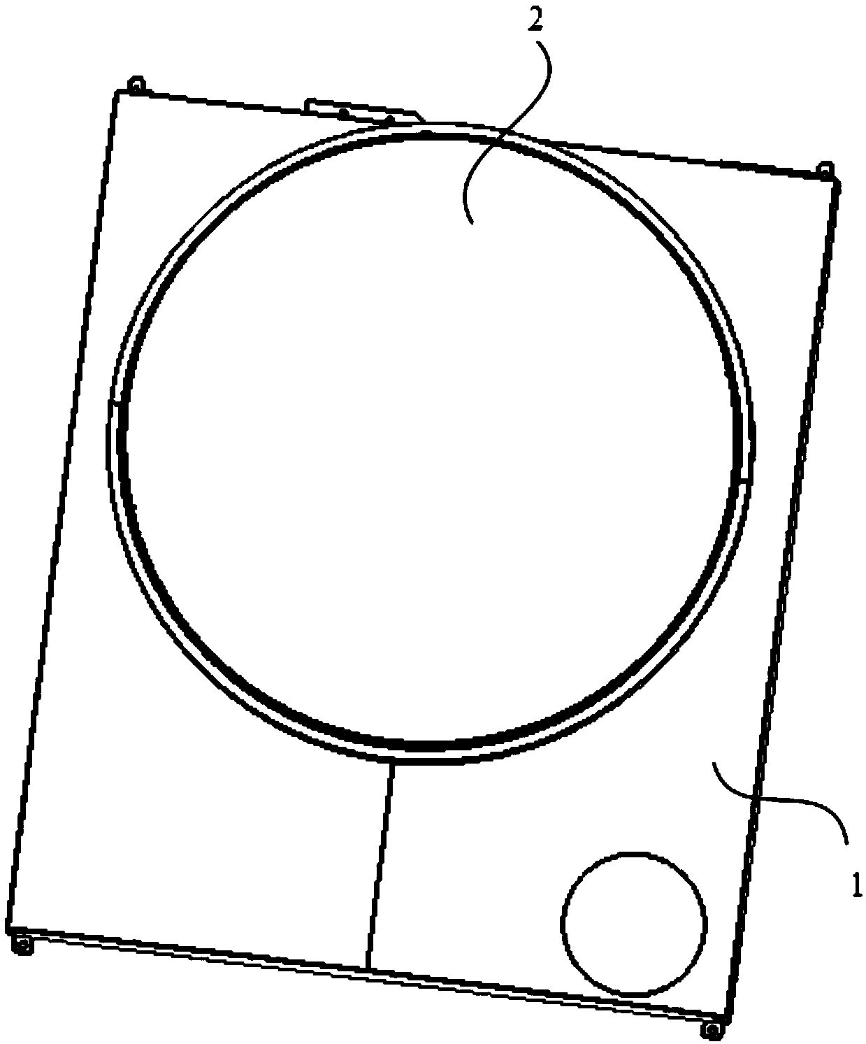
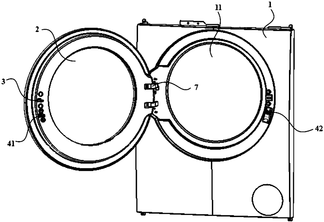
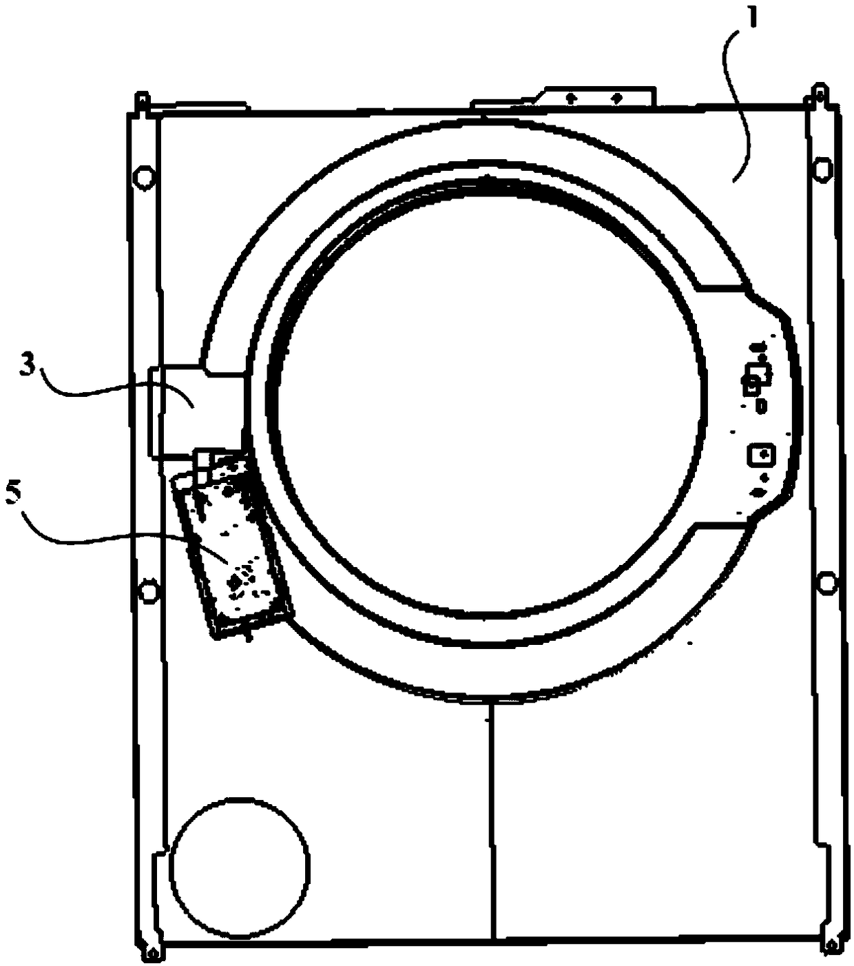
[0053] figure 1 It is a schematic diagram of the structure of the electrical appliance in the closed state provided in this embodiment, figure 2 The schematic diagram of the structure of the electrical appliance provided in this embodiment in the state of opening the door, such as figure 1 and figure 2As shown, the present embodiment provides an electrical appliance, comprising a housing 1, an opening 11 is provided on one side of the housing 1; The casing 1 rotates to open or close the opening 11; the door l...


PUM


Abstract

The invention belongs to the technical field of domestic electric appliances, and particularly discloses a push-and-pull mechanism and an electric appliance with the push-and-pull mechanism. The push-and-pull mechanism comprises a push-and-pull executing mechanism and a push-and-pull clutching mechanism; the push-and-pull executing mechanism comprises a push-and-pull part and a push-and-pull driving assembly which are separately arranged; the push-and-pull clutching mechanism is connected with the push-and-pull driving assembly and can drive the push-and-pull driving assembly to move between afirst position and a second position; when the push-and-pull driving assembly is located at the first position, the push-and-pull driving assembly can be in contact with the push-and-pull part and drive the push-and-pull part to move, and when the push-and-pull driving assembly is located at the second position, the push-and-pull driving assembly cannot be in contact with the push-and-pull part.By means of the push-and-pull mechanism, the electric appliance with the push-and-pull mechanism can be compatible to the automatic door opening and closing operation and manual door opening and closing operation, the running reliability of the electric appliance can be improved, the service life of the electric appliance can be prolonged, and the user experience is good.

Description

technical field [0001] The invention relates to the technical field of household appliances, in particular to a push-pull mechanism and an appliance. Background technique [0002] As an essential household appliance in most families, the washing machine has the functions of washing, drying or deodorizing clothing, towels, sheets and other clothing materials, saving labor for users and improving the quality of life of users. [0003] The prior art discloses a drum washing machine and a control method thereof. The drum washing machine includes a housing, an opening is provided on the housing, and a door is provided at the opening. One side of the door is hinged to the housing through a hinge, and the other side is fixed. There is a door hook, and a groove is provided on the corresponding door hook on the housing, and a first driving mechanism and a second driving mechanism are also included. The first driving mechanism can drive the door hook to move away from or close to the ...

Claims


Application Information

Patent Timeline
Patent Type & Authority Applications(China)
IPC IPC(8): D06F39/14D06F58/20A47L15/42
CPCA47L15/4259D06F39/14D06F58/20
Inventor 乔坤
Owner 乔坤
Learn More