Pulse accelerator control device

A throttle control and pulse technology, which is applied in engine control, machine/engine, mechanical equipment, etc., can solve the problems of wasting gasoline and high cost, and achieve the effect of saving electricity or fuel consumption

Inactive Publication Date: 2018-11-20
太仓市夏米粒信息技术有限公司
View PDF0 Cites 0 Cited by
  • Summary
  • Abstract
  • Description
  • Claims
  • Application Information

AI Technical Summary

Problems solved by technology

However, if both the foot throttle and the hand throttle use electronic throttle, the cost will be very high
[0003] In addition, the size of the traditional accelerator is controlled by the stepping depth of the pedal. When the stepping reaches a certain depth, the fuel supply of the car is at a constant value. It will lead to a drop in vehicle speed, so the continuous fuel supply method of the transmission wastes a lot of gasoline

Method used


Image

  • Pulse accelerator control device

Examples


Embodiment

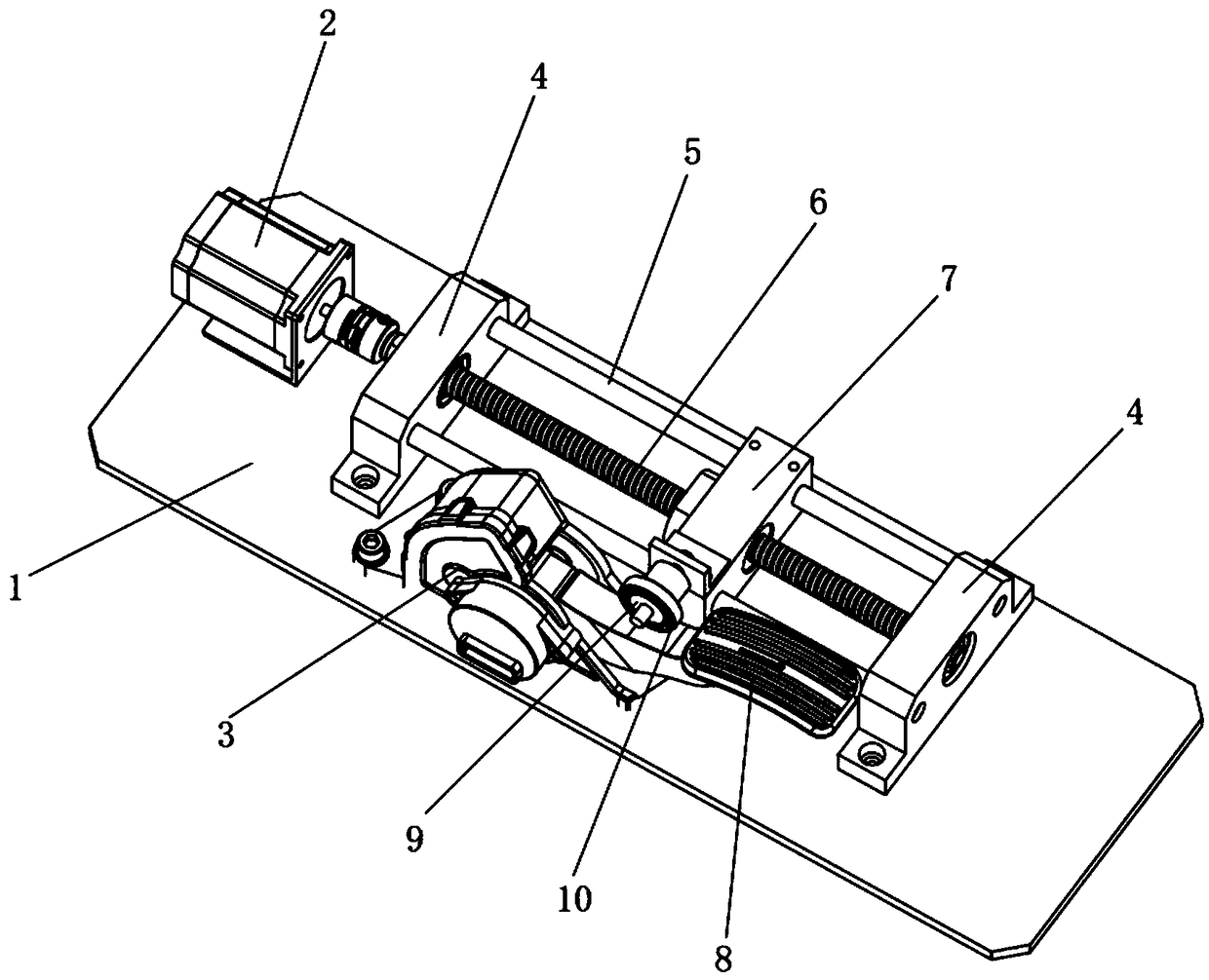
[0016] The invention discloses a pulse throttle control device, such as figure 1 As shown, it includes: a base plate 1, and a stepper motor 2, a support frame 4 and a potential control sensor 3 arranged on the base plate 1; the support frame 4 is provided with a slide bar 5 and a transmission screw 6; the slide bar 5 Set side by side on the support frame 4; the transmission screw mandrel 6 is rotatably installed on the support frame 4, and one end is connected with the output shaft of the stepper motor 2; block 7; the slider 7 can reciprocally slide along the slide bar 5; the slider 7 is provided with a pressing wheel 9; the potential control sensor 3 is provided with a pressing bar 8 linked with it; the pressing wheel 9 It is in conflict with the pressure rod 8 and can slide along its surface; the pressure wheel 9 is sleeved with a bearing 10; the pressure rod 8 is arranged in an inclined shape.

[0017] Preferably, when the present invention is applied to an electric vehicl...


PUM


Abstract

The invention discloses a pulse accelerator control device, and belongs to the technical field of accelerator control. The pulse accelerator control device comprises a bottom plate, a stepper motor, asupporting frame and a potential control sensor, wherein the stepper motor, the supporting frame and the potential control sensor are arranged on the bottom plate. The supporting frame is provided with sliding rods and a transmission lead screw. The sliding rods are arranged on the supporting frame in parallel. The transmission lead screw is rotatably mounted on the supporting frame, and one endof the transmission lead screw is in transmission connection with an output shaft of the stepper motor. The transmission lead screw is provided with a sliding block in threaded connection with the transmission lead screw. The sliding block can slide in a reciprocating mode along the sliding rods and is provided with a pressing wheel. The potential control sensor is provided with a pressing rod inlinkage with the potential control sensor. The pressing wheel makes contact with the pressing rod in an abutting mode and can slide along the surface of the pressing rod. According to the pulse accelerator control device, the arranged stepper motor drives the transmission lead screw to rotate so as to be in linkage with the pressing wheel to move in a horizontal reciprocating mode, the pressing rod is pressed to swing in a reciprocating mode, thus the inner potential of the potential control sensor is changed in a reciprocating mode, a vehicle accelerator is controlled to be changed in a pulsemode, the power consumption or fuel consumption of a vehicle is greatly saved, and the pulse accelerator control device has great market economic value.

Description

technical field [0001] The invention relates to the technical field of throttle control, in particular to a pulse throttle control device. Background technique [0002] With the development of society, the requirements for exhaust emissions are getting higher and higher. In the field of construction machinery, electronically controlled engines are used more and more, and electronic throttle control technology is also used more and more. The accelerator pedal also needs to be set with a hand accelerator to adapt to different working conditions. For example, for a loader, the accelerator is required to be changed during shoveling operations. Usually, the foot accelerator is used, but when the loader is equipped with attachments, the accelerator is required to be Fixed, this situation is usually using the hand throttle. However, if both the foot accelerator and the hand accelerator adopt the electronic accelerator, the cost will be very high. [0003] In addition, the size of...

Claims


Application Information

Patent Timeline
Patent Type & Authority Applications(China)
IPC IPC(8): F02D11/10
CPCF02D11/10F02D2011/104
Inventor 方夏仙
Owner 太仓市夏米粒信息技术有限公司
Why Eureka
Try Eureka