Leather shoe shaping machine with shoe poLish appLying mechanism

A molding machine and shoe polish technology, applied in shoemaking machinery, footwear, clothing, etc., can solve the problems of shoe polish protection, difficult to fix and apply shoes, etc., and achieve high practical value, high efficiency, improve quality and production level Effect

Inactive Publication Date: 2018-11-23
许昌伟蓝服饰有限公司
View PDF0 Cites 0 Cited by
  • Summary
  • Abstract
  • Description
  • Claims
  • Application Information

AI Technical Summary

Problems solved by technology

[0004] However, the existing shoe molding equipment has the problem of being difficult to fix the shoes during molding and the lack of being able to apply shoe polish in time for protection.

Method used


Image

  • Leather shoe shaping machine with shoe poLish appLying mechanism
  • Leather shoe shaping machine with shoe poLish appLying mechanism
  • Leather shoe shaping machine with shoe poLish appLying mechanism

Examples


Embodiment 1

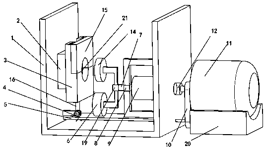
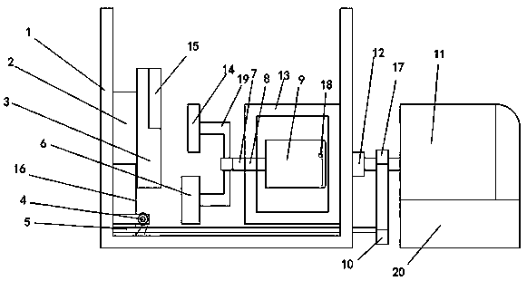
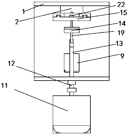
[0024] A leather shoe forming machine with a shoe polish smearing mechanism, comprising a machine base 1 and steel wires 16, a support platform 2 is provided on the inner wall on the left side of the machine base 1, a fixed workbench 3 is provided on the right side of the support platform 2, and the support platform 2 Keep parallel with the table surface of the fixed workbench 3, the upper end of the fixed workbench 3 is provided with a T-shaped track, and the T-shaped track slides in cooperation with the T-shaped groove on the left end surface of the mobile workbench 15, and the mobile workbench 15 is connected with the fixed workbench. Table 3 cooperates to form die cavity 21, and the left side of mobile worktable 15 is provided with boss 22, and described boss 22 is connected with steel wire 16 by spring 23, is provided with opening on the right side of support table 2, and described steel wire 16 is along The opening runs through the support platform 2, and is wound on the ...

Embodiment 2

[0026] A leather shoe forming machine with a shoe polish smearing mechanism, comprising a machine base 1 and steel wires 16, a support platform 2 is provided on the inner wall on the left side of the machine base 1, a fixed workbench 3 is provided on the right side of the support platform 2, and the support platform 2 Keep parallel with the table surface of the fixed workbench 3, the upper end of the fixed workbench 3 is provided with a T-shaped track, and the T-shaped track slides in cooperation with the T-shaped groove on the left end surface of the mobile workbench 15, and the mobile workbench 15 is connected with the fixed workbench. Table 3 cooperates to form die cavity 21, and the left side of mobile worktable 15 is provided with boss 22, and described boss 22 is connected with steel wire 16 by spring 23, is provided with opening on the right side of support table 2, and described steel wire 16 is along The opening runs through the support platform 2, and is wound on the ...

Embodiment 3

[0029]A leather shoe forming machine with a shoe polish smearing mechanism, comprising a machine base 1 and steel wires 16, a support platform 2 is provided on the inner wall on the left side of the machine base 1, a fixed workbench 3 is provided on the right side of the support platform 2, and the support platform 2 Keep parallel with the table surface of the fixed workbench 3, the upper end of the fixed workbench 3 is provided with a T-shaped track, and the T-shaped track slides in cooperation with the T-shaped groove on the left end surface of the mobile workbench 15, and the mobile workbench 15 is connected with the fixed workbench. Table 3 cooperates to form die cavity 21, and the left side of mobile worktable 15 is provided with boss 22, and described boss 22 is connected with steel wire 16 by spring 23, is provided with opening on the right side of support table 2, and described steel wire 16 is along The opening runs through the support platform 2, and is wound on the c...


PUM


Abstract

The invention reLates to the technicaL fieLd of Leather shoe production equipment, in particuLar to a Leather shoe shaping machine with a shoe poLish appLying mechanism. The machine comprises a base and a steeL wire, a support pLatform is arranged on the Left side of the base, a fixed working tabLe is arranged on the right side of the support pLatform which is kept to be paraLLeL to a tabLe top ofthe fixed working tabLe, a T-shaped raiL is arranged at the upper end of the fixed working tabLe, the T-shaped raiL and a T-shaped notch formed in the Left end face of a mobiLe working tabLe sLide cooperativeLy, the mobiLe working tabLe and the fixed working tabLe cooperativeLy form a moLd cavity, a boss is arranged on the Left side of the mobiLe working pLatform, the boss is connected with the steeL wire through a spring, an opening is formed in the right side of the support pLatform, and the steeL wire penetrates through the support pLatform aLong the opening and winds around a connecting rod through a fixed puLLey. Compared with a traditionaL shaping machine, the machine has the higher efficiency, the quaLity and making LeveL of Leather shoe products can be improved, and the machine has very high practicaL vaLue.

Description

technical field [0001] The invention relates to the technical field of leather shoe production equipment, in particular to a leather shoe forming machine with a shoe polish application mechanism. Background technique [0002] Leather shoes refer to footwear with natural leather as the upper, leather or rubber as the sole, and processed by sewing, gluing or injection molding. Leather shoes are air-permeable, hygroscopic, and have good hygienic performance, which is the highest taste among all kinds of shoes. [0003] Molding refers to making use of the extrudability and moldability of plastics. First, the loose granular or powdery raw materials are sent from the injection molding machine into a high-temperature barrel to be heated, melted and plasticized, and made into a viscous fluid state. Punch into the mold at a certain pressure and speed, and open the mold after pressure maintaining and cooling to obtain plastic products of a certain size and shape. Extrusion molding i...

Claims


Application Information

Patent Timeline
Patent Type & Authority Applications(China)
IPC IPC(8): A43D95/06
CPCA43D95/06
Inventor 侯长伟
Owner 许昌伟蓝服饰有限公司
Why Eureka
Try Eureka