Supercharge Your Innovation With Domain-Expert AI Agents!

Stirrer device

A stirrer and stirring rod technology, which is applied in the fields of agitator devices and electric agitator devices, can solve the problems of decreased output, poor quality, single function, etc., and achieve the effect of increasing functions

Inactive Publication Date: 2018-11-23
陈超
View PDF6 Cites 0 Cited by
  • Summary
  • Abstract
  • Description
  • Claims
  • Application Information

AI Technical Summary

Problems solved by technology

[0004] In view of the above problems, the present invention provides a stirrer device, which solves the problem of single function, incapable of automatic production, resulting in poor quality of output and poor quality

Method used


Image

  • Stirrer device
  • Stirrer device
  • Stirrer device

Examples


Embodiment 1

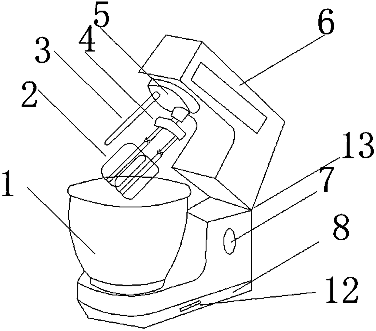
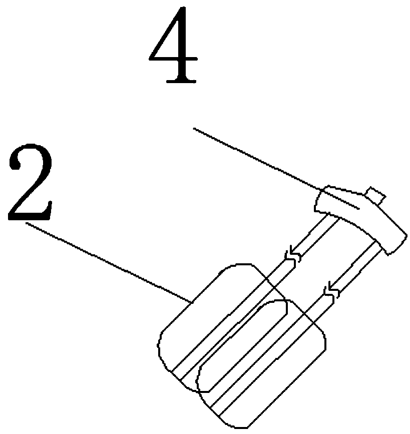
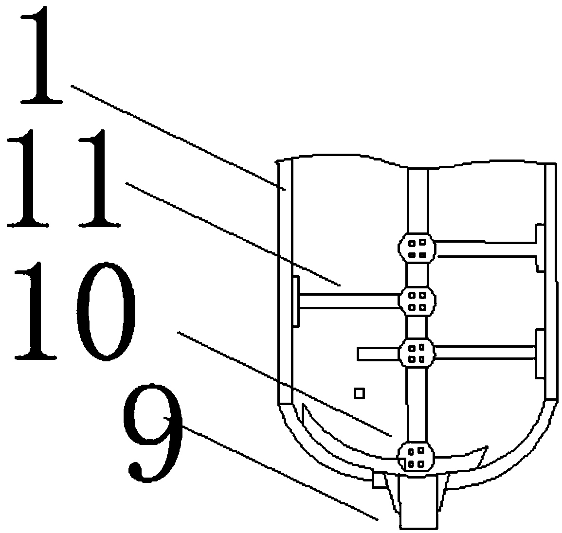
[0014] refer to figure 1 , figure 2 , image 3 and Figure 4 , a stirrer device, characterized in that: its structure includes a liquid container 1, an egg beater 2, a heating rod 3, a rotating chuck 4, a rotating bayonet 5, a handle 6, a temperature adjustment button 7, a base 8, a base Chuck 9, main shaft connection bayonet 10, stirring rod 11, start switch 12, connecting shaft 13; said egg beater 2, stirring rod 11, heating rod 3, handle 6, main shaft connection bayonet 10, liquid container 1 , the base chuck 9, the start switch 12, and the base 8 are sequentially connected to the agitator from top to bottom. fixed on one side, the stirring rod 11 is connected with the rotary chuck 4, the egg-beating rod 2 and the stirring rod 11 are connected with the handle 6 through the rotary chuck 4, and the heating rod 3 is connected with the rotary bayonet 5 The handle 6 is connected to the base 8 through a connecting shaft 13 . The stirring rod 11 is fixed to the stirring rod ...


PUM


Abstract

The invention discloses a stirrer device. The stirrer device structurally comprises a liquid container, an egg beating rod, a heating rod, a rotary chuck, a rotary bayonet, a handle, a temperature adjusting button, a base, a base chuck, a main shaft connecting bayonet, a stirring rod, a starting switch and a connecting shaft; the egg beating rod, the stirring rod, the heating rod, the handle, themain shaft connecting bayonet, the liquid container, the base chuck, the starting switch and the base are sequentially connected on the stirrer from top to bottom; the liquid container is fixed to thebase through the base chuck, the egg beating rod and the rotary chuck are fixed to one side, and the stirring rod is connected with the rotary chuck; the egg beating rod and the stirring rod are connected through the rotary chuck and the handle, and the heating rod is fixed to the rotary bayonet.

Description

technical field [0001] The invention relates to the field of electric stirrer devices, in particular to a stirrer device. Background technique [0002] Agitator is a commonly used stirring and blending device in food processing, which is used to beat viscous slurry, such as syrup, batter, egg liquid, cheese, etc. With the continuous improvement of the social economy and the continuous improvement of people's requirements for the quality of life, it has gradually become popular. [0003] The prior art discloses a stirring device with an application number of 201320695706.5, which includes a stirring shaft, the lower end of which is symmetrically fixed to a bracket by means of a fixed sleeve, and the bracket is fixed to a stirring blade; the stirring blade has a V-shaped structure, and the lower surface of the stirring blade is fixed Connect the support plate. The present invention has a simple structure, and the resin is stirred through the combination of a V-shaped stirrin...

Claims


Application Information

Patent Timeline
IPC IPC(8): A47J43/044A47J43/07A47J36/24
CPCA47J36/2483A47J43/044A47J43/0711
Inventor 不公告发明人
Owner 陈超
Features
  • R&D
  • Intellectual Property
  • Life Sciences
  • Materials
  • Tech Scout
  • Unparalleled Data Quality
  • Higher Quality Content
  • 60% Fewer Hallucinations
Learn More