Urethral dilator

A technique for dilating the urethra and dilating tubes, applied in the field of medical devices, can solve problems such as increasing patient pain and urethral scraping, and achieve the effect of relieving pain and relaxing the process

Pending Publication Date: 2018-11-23
SHENZHEN UNIV +1
View PDF8 Cites 2 Cited by
  • Summary
  • Abstract
  • Description
  • Claims
  • Application Information

AI Technical Summary

Problems solved by technology

[0003] The newly installed dilation tube will continue to cause scraping and other pressure on the entire inner wall of the urethra during the sleeve installation process, which increases the pain of the patient. If the multi-layer dilation tube is installed, the patient will suffer multiple times of pain

Method used


Image

  • Urethral dilator
  • Urethral dilator
  • Urethral dilator

Examples


Embodiment Construction

[0024] In order to have a clearer understanding of the technical features, purposes and effects of the present invention, the specific implementation manners of the present invention will now be described in detail with reference to the accompanying drawings.

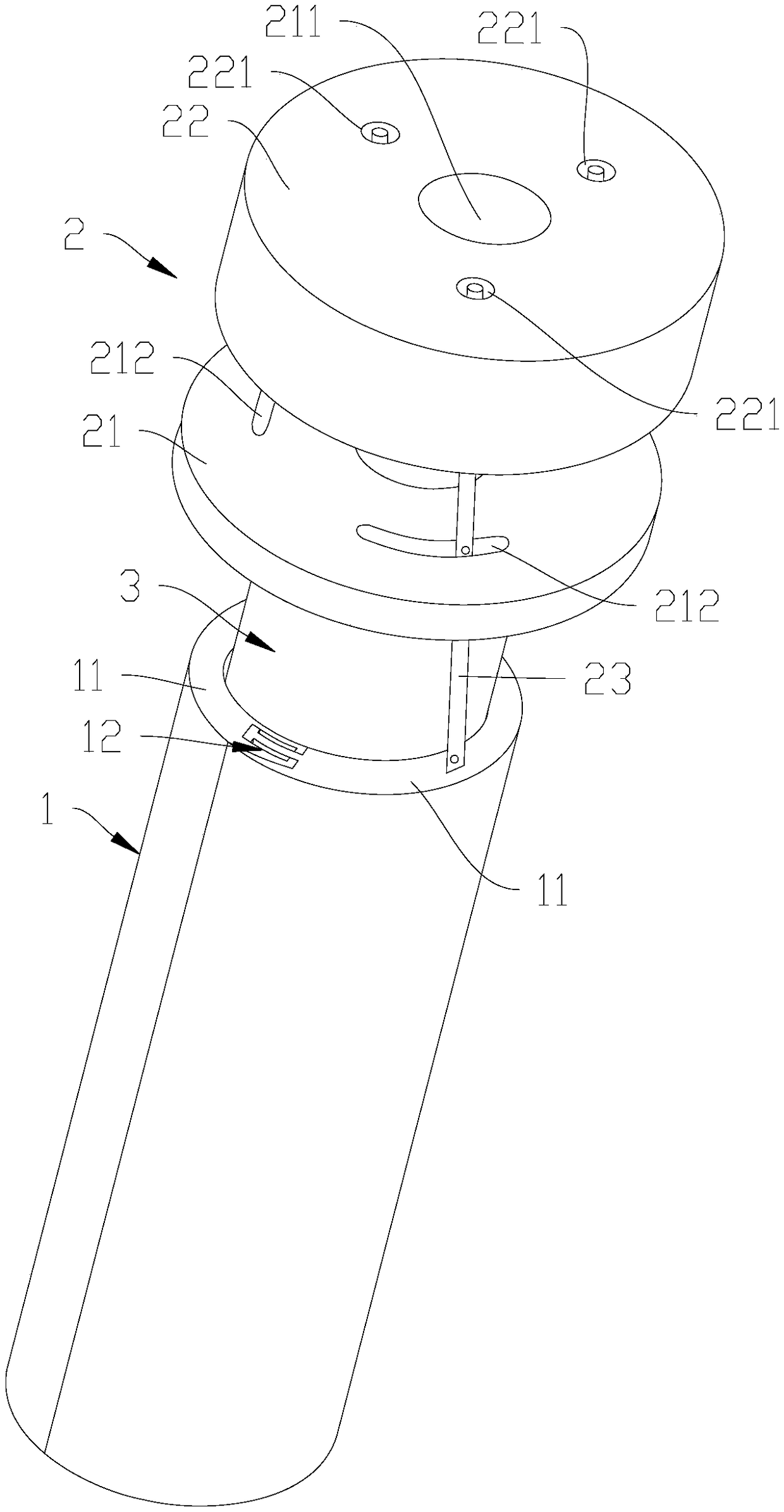
[0025] Such as Figure 1 to Figure 3 As shown, the urethral dilator in a preferred embodiment of the present invention includes a dilation tube 1 and a driving assembly 2 arranged at one end of the dilation tube 1 .

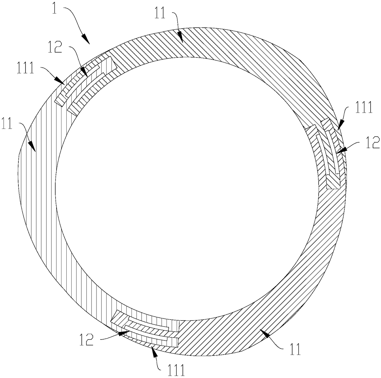
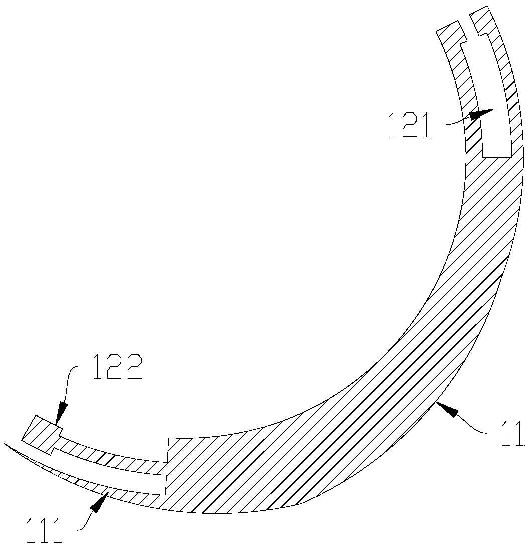
[0026] Further, the expansion tube 1 includes three tube pieces 11 spliced ​​and connected in the circumferential direction, and an adjustment structure 12 capable of adjusting the circumferential offset position is provided between two adjacent tube pieces 11 . The driving assembly 2 is correspondingly connected with the segments 11, so that the circumferential stagger angle between two adjacent segments 11 can be adjusted by the driving assembly 2, so that the outer diameter of the expansion tube 1 can b...


PUM


Abstract

The invention relates to a urethral dilator. The urethral dilator comprises a dilated tube and a driving assembly arranged at one end of the dilated tube; the dilated tube comprises at least two ductpieces in splicing connection, and an adjusting structure capable of circumferential staggered position is arranged between two adjacent duct pieces; and the driving assembly is correspondingly connected with the duct pieces to adjacent the circumferential staggered angle between the two adjacent duct pieces to make the external diameter of the dilated tube increase or decrease. The urethral dilator performs urethral dilatation, the dilated tube and one end opposite to the driving assembly can be inserted into the urethra, the driving assembly operates from the outer portion of the urethra tomake the external diameter of the dilated tube increase to achieve the urethral dilatation; in the whole dilatation process, insertion action is only needed once, no any part is involved between the outer wall of the dilated tube and the inner wall of the urethra, so that the inner wall of the urethra can be scraped or subjected to other oppression, the urethra is dilated naturally, and the process is more relaxed, thereby being capable of alleviating the pain of patients.

Description

technical field [0001] The present invention relates to medical equipment, more particularly, relates to a kind of urethral dilator. Background technique [0002] The urethral dilating device in the related art usually inserts a dilating piece first, and then puts a new dilating tube on the outside of the dilating piece that has been inserted, so as to achieve the effect of dilating the urethra. [0003] The newly installed dilation tube will continue to cause scraping and other pressure on the entire inner wall of the urethra during the sleeve installation process, which increases the pain of the patient. If the multi-layer dilation tube is installed, the patient will suffer multiple times of pain . Contents of the invention [0004] The technical problem to be solved by the present invention is to provide a urethral dilator. [0005] The technical solution adopted by the present invention to solve the technical problem is: to construct a urethral dilator, including a d...

Claims


Application Information

Patent Timeline
Patent Type & Authority Applications(China)
IPC IPC(8): A61M29/00
CPCA61M29/00A61M2210/1078
Inventor 王祥卫王滨
Owner SHENZHEN UNIV
Why Eureka
Try Eureka