Automatic U-shaped part truing device

A shaping device, U-shaped technology, applied in the direction of feeding device, positioning device, storage device, etc.

Active Publication Date: 2018-11-23
姚奇圣
View PDF5 Cites 0 Cited by
  • Summary
  • Abstract
  • Description
  • Claims
  • Application Information

AI Technical Summary

Problems solved by technology

In order to improve the accuracy of the U-shaped parts, it is necessary to reshape the U-shaped parts, so that the U-shaped parts meet the requirements of the specified size. However, the prior art lacks a device for reshaping the U-shaped parts, which urgently needs to be solved.

Method used


Image

  • Automatic U-shaped part truing device
  • Automatic U-shaped part truing device
  • Automatic U-shaped part truing device

Examples


Embodiment Construction

[0016] The present invention will be further described below in conjunction with the accompanying drawings and specific embodiments.

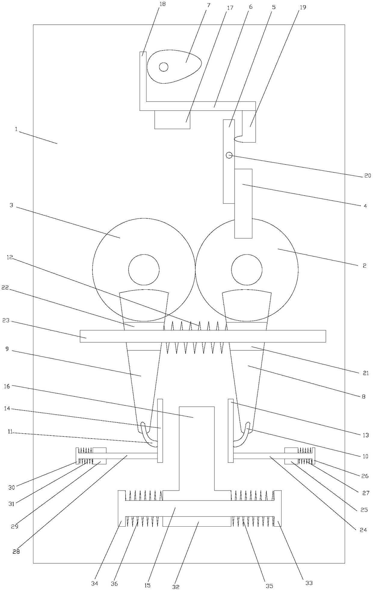
[0017] As shown in the figure, the automatic U-shaped piece shaping device of the present invention includes a workbench 1, on which a first gear 2 and a second gear 3 that mesh with each other are rotatably connected, and the first gear 2 is rotatably connected to the On the workbench 1, the second gear 3 is rotatably connected to the workbench 1 through the second rotary shaft. The drive plate 5 is connected to the upper part for rotation, and the slide plate 6 for pulling the drive plate 5 to rotate is slidably connected to the workbench 1. The lower end of the drive plate 5 is in close contact with the plectrum 4, and the workbench 1 is provided with a cam for driving the slide plate 6 to slide. 7. The workbench 1 is provided with a motor for driving the cam 7 to rotate, and the motor is connected to an external power supply to work; the fi...


PUM


Abstract

The invention discloses an automatic U-shaped part truing device. The device comprises a workbench. A first gear and a second gear engaged with the first gear are rotationally connected to the workbench. A plectrum is arranged on the first gear. A transmission plate is rotationally connected to the workbench. The workbench is in sliding connection with a sliding plate used for pulling the transmission plate to rotate. The lower end of the transmission plate abuts against the plectrum tightly. A cam used for driving the sliding plate to slide is arranged on the workbench. A first oscillating bar and a second oscillating bar are arranged on the first gear and the second gear correspondingly. A first pressure claw and a second pressure claw are arranged at the lower ends of the first oscillating bar and the second oscillating bar correspondingly, and a reset pressure spring is arranged between the first oscillating bar and the second oscillating bar. A first limit plate used for abuttingagainst the first pressure claw tightly and a second limit plate used for abutting against the second pressure claw tightly are connected to the workbench in a sliding mode. The first limit plate andthe second limit plate are located in a gap between the first pressure claw and the second pressure claw. The automatic U-shaped part truing device can be used for improving the precision of U-shapedparts.

Description

technical field [0001] The invention relates to the field of mechanical automatic processing, in particular to an automatic U-shaped piece shaping device. Background technique [0002] In the process of producing and processing U-shaped parts, it is usually realized by stamping dies. It specifically includes an upper mold base and a lower mold base. The lower mold base is provided with a die for accommodating the metal sheet. Through the connection of the guide post, the upper die seat is slidingly connected to the guide post; that is to say, the stamping is completed when the punch is lowered and matched with the die, and then a U-shaped part consistent with the shape of the die is obtained. However, once the punch is pulled out from the die, that is, the punch and the die are parted, after the U-shaped part is taken out, it has a certain springback due to the metal properties of the plate, such as figure 1 shown. In order to improve the precision of the U-shaped piece, ...

Claims


Application Information

Patent Timeline
Patent Type & Authority Applications(China)
IPC IPC(8): B21D3/10B21D43/00
CPCB21D3/10B21D43/00
Inventor 许雪娇
Owner 姚奇圣
Why Eureka
Try Eureka