Pipe bending tooling

A technology for bending and pipe fittings, applied in forming tools, manufacturing tools, metal processing equipment, etc., can solve the problems of reducing the qualified rate of elbows, difficult to control the distance between two bends, etc., and achieve the effect of improving the qualified rate

Pending Publication Date: 2018-11-23
重庆祥越管道配件制造有限公司
View PDF0 Cites 6 Cited by
  • Summary
  • Abstract
  • Description
  • Claims
  • Application Information

AI Technical Summary

Problems solved by technology

[0004] The purpose of the present invention is to provide a pipe fitting bending tool, which solves the problem in the prior art that the distance between the two bends is difficult to control when bending the two ends of the pipe fitting, resulting in a decrease in the qualified rate of the bent pipe

Method used


Image

  • Pipe bending tooling
  • Pipe bending tooling
  • Pipe bending tooling

Examples


Embodiment Construction

[0022] The present invention will be described in further detail below by means of specific embodiments:

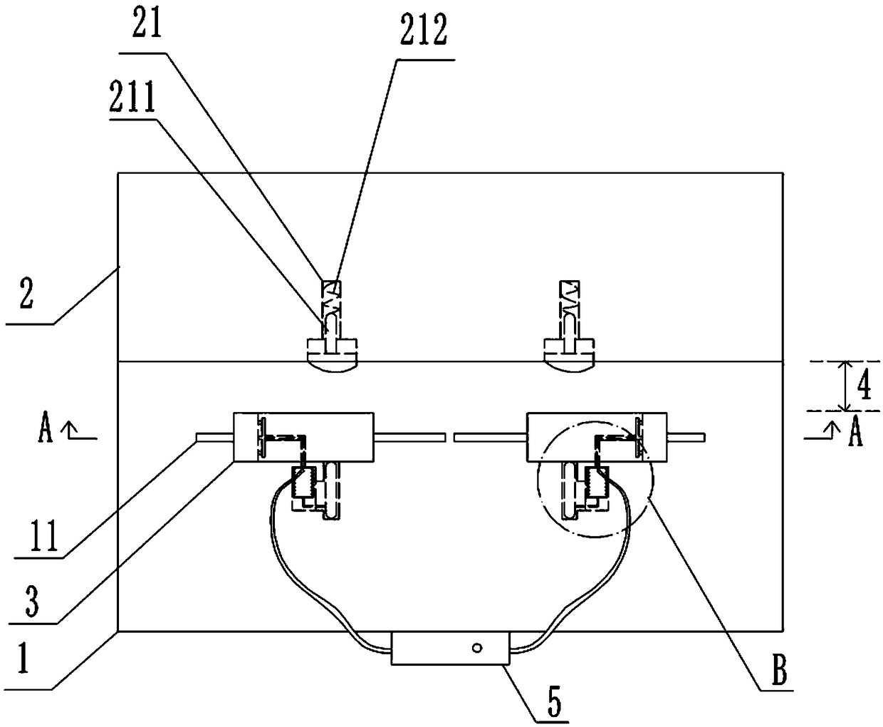
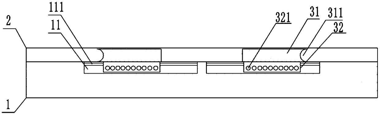
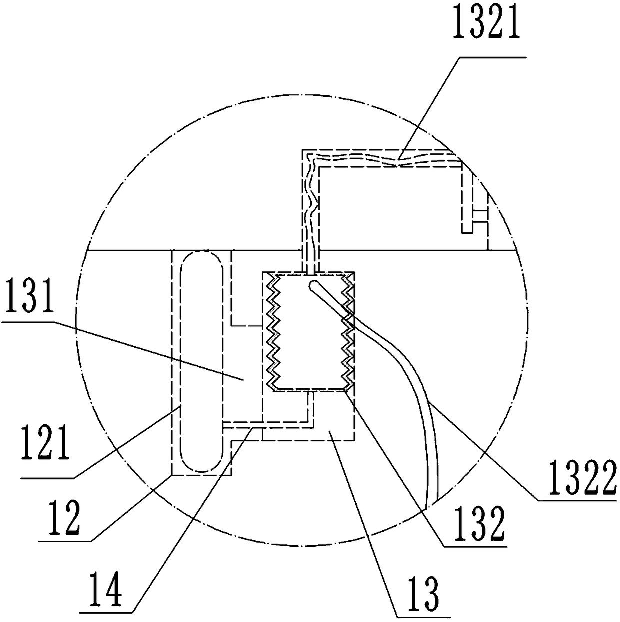
[0023] The reference signs in the drawings of the description include: processing table 1, strip chute 11, strip side groove 111, positioning cavity 12, positioning column 121, extrusion cavity 13, connecting hole 131, elastic air bag 132, liquid outlet pipe 1321, liquid inlet pipe 1322, L-shaped push rod 14, positioning platform 2, sliding hole 21, slide block 211, spring 212, adjustment block 3, block body 31, arc groove 311, sliding block 32, positioning hole 321, place Channel 4, storage tank 5.

[0024] The embodiment is basically as figure 1 , figure 2 and image 3 As shown, the pipe bending tooling includes a processing table 1, a positioning table 2 and an adjustment block 3 are arranged on the processing table 1, the positioning table 2 is fixedly connected to one side of the processing table 1, and the adjustment block 3 is connected to the other side of the...


PUM


Abstract

The invention relates to the technical field of pipe processing, and particularly discloses a pipe bending tooling, which comprises a processing table, a positioning table and adjusting blocks are arranged on the processing table, and a placing channel for placing a pipe is formed between the adjusting blocks and the positioning table; the number of the adjusting blocks is two, and the two adjusting blocks are in sliding connection with the processing table; a positioning hole is formed in the lower part of each adjusting block; the end part of each adjusting block is provided with an arc-shaped groove; a sliding hole is arranged in the positioning table, a sliding block is slidably connected in the sliding hole, and a spring is fixed between the sliding block and the sliding hole wall; asliding cavity and a positioning cavity are arranged in the processing table; a positioning column used for being inserted in a positioning hole is slidably connected in the positioning cavity, the two ends of the sliding cavity are respectively communicated with the sliding hole and the positioning cavity; a push rod is slidably connected in the sliding cavity, the two ends of the push rod are bent and fixedly connected with the sliding block and the positioning column. According to the scheme, the problem that the distance between the two bending parts of the pipe is difficult to control when the two ends of the pipe are bent in the prior art, which causes low qualification rate of the bent pipe, is solved.

Description

technical field [0001] The invention relates to the technical field of pipeline processing, in particular to a pipe fitting bending tool. Background technique [0002] The elbow is an essential part of the system, which has the characteristics of no dead angle and easy cleaning. The bending treatment of both ends of the pipe fittings is completed in the pipe bending machine. Generally, the pipe bending machine is composed of wheel dies, clamping dies, guide dies, mandrels and other components; during the bending process, only the mandrel needs to be removed from the The bent end is inserted, and then the end to be bent is put into the clamping mold; the worker holds the other end by hand, and then bends the steel end pipe to form an elbow; the method of bending the other end of the pipe fitting is the same as above. [0003] The prior art has the following technical problems: 1. During the bending and forming process, the inner side of the pipe is squeezed and frictional, w...

Claims


Application Information

Patent Timeline
Patent Type & Authority Applications(China)
IPC IPC(8): B21D7/00B21D7/16B21D9/00B21D9/16B21D37/18
CPCB21D7/00B21D7/167B21D9/00B21D9/16B21D37/18
Inventor 张祥春
Owner 重庆祥越管道配件制造有限公司
Why Eureka
Try Eureka