A welding machine and automatic welding method based on vision positioning

A visual positioning, welding machine technology, applied in welding equipment, auxiliary welding equipment, welding/cutting auxiliary equipment, etc., can solve problems such as welding defects, reduce hazards, reduce production costs, and improve welding quality and efficiency.

Active Publication Date: 2020-08-11
高密鼎泰锅炉配件有限公司
View PDF5 Cites 0 Cited by
  • Summary
  • Abstract
  • Description
  • Claims
  • Application Information

AI Technical Summary

Problems solved by technology

[0005] An object of the present invention is to overcome the deficiencies of the prior art and provide a welding machine based on visual positioning, which can accurately and automatically position the workpiece to be welded and avoid welding defects caused by inaccurate positioning

Method used


Image

  • A welding machine and automatic welding method based on vision positioning
  • A welding machine and automatic welding method based on vision positioning
  • A welding machine and automatic welding method based on vision positioning

Examples


Embodiment Construction

[0038] The specific implementation manners of the present invention will be further described in detail below in conjunction with the accompanying drawings.

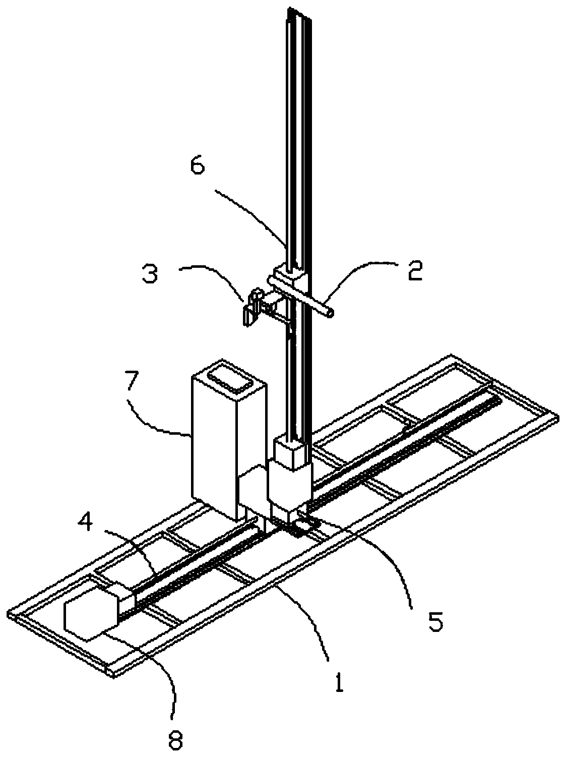
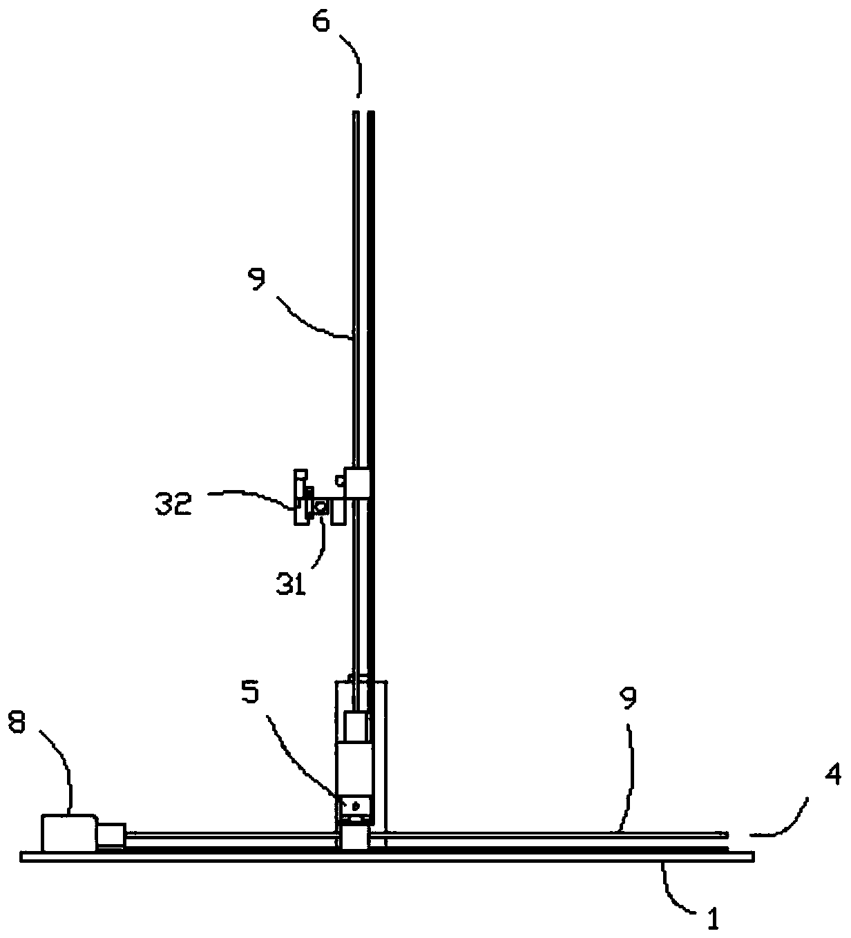
[0039] Such as figure 1 and figure 2 As shown, a welding machine based on vision positioning includes a base 1 , a motion mechanism, a welding torch module 2 and a vision positioning module 3 . The base 1 is used to support other components, and the movement mechanism is installed on the base 1 and connected with the welding torch module 2 for driving the welding torch module 2 to move in front, back, left and right and up and down directions.

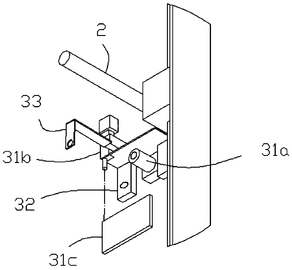
[0040] combine image 3 and Figure 4 As shown, the visual positioning module 3 includes an image acquisition module 31, an illumination module 32, a reference object and an image processing device; the image acquisition module 31 is fixedly connected to the welding torch module 2, and is used to acquire image information of workpieces to be welded; The lighting module 32 co...


PUM


Abstract

The invention relates to a welding machine based on visual localization. The welding machine comprises a base, a movement mechanism mounted on the base, a welding gun module connected with the movement mechanism and a visual localization module, wherein the visual localization module comprises an image acquisition module which is fixedly connected with the welding gun module and is used for acquiring image information of a workpiece to be welded, an illumination module which is matched with the image acquisition module and is used for illuminating the workpiece to be welded, a reference objectwhich has a determined coordinate value, is arranged between the workpiece to be welded and the image acquisition module and is located in a photographing range of the image acquisition module, and an image processing device which is connected with the image acquisition module and is configured to identify and acquire a characteristic pattern in an image, compare the characteristic pattern with the coordinate value of the reference object, calculate an effective coordinate value of the characteristic pattern and transmit the effective coordinate value to the movement mechanism. The inventionfurther relates to an automatic welding method by utilizing the welding machine based on the visual localization, and automatic localization and welding can be realized.

Description

technical field [0001] The invention relates to the field of automatic welding, in particular to a welding machine and an automatic welding method based on vision positioning. Background technique [0002] At present, heat exchanger welding is mostly manual welding, and the radiation and smoke generated by traditional welding are relatively harmful to workers. The existing heat exchanger welding machine adopts contact welding, that is, after the tubes are threaded, each tube needs to be welded manually, and then a positioning column with a taper is inserted into the tubes for positioning and circular welding, among which , Most of the vertical welding is argon arc welding, and most of the flat welding is second welding. This welding method has a low degree of automation and requires manual positioning, which cannot save labor or reduce the harm to the human body. [0003] The biggest difficulty in automatic welding of heat exchangers lies in positioning. Due to manual mark...

Claims


Application Information

Patent Timeline
Patent Type & Authority Patents(China)
IPC IPC(8): B23K37/00B23K37/02
CPCB23K37/00B23K37/0211B23K37/0247
Inventor 孙高森郭龙
Owner 高密鼎泰锅炉配件有限公司
Why Eureka
Try Eureka