Cutting guiding device

A guiding device and cutting technology, which is applied in metal processing and other directions, can solve the problems of different lengths of finished products, flying out of the working track, and large cutting force.

Inactive Publication Date: 2018-11-23
FOSHAN MEIRUN RUBBER TECH DEV CO LTD
View PDF0 Cites 0 Cited by
  • Summary
  • Abstract
  • Description
  • Claims
  • Application Information

AI Technical Summary

Problems solved by technology

[0002] The existing cutting machine or punching machine needs to manually push and pull the workpiece to reach the station when cutting t

Method used


Image

  • Cutting guiding device
  • Cutting guiding device

Examples


Embodiment Construction

[0011] The specific embodiments of the present invention will be further described below in conjunction with the accompanying drawings. It should be noted here that the descriptions of these embodiments are used to help understand the present invention, but are not intended to limit the present invention. In addition, the technical features involved in the various embodiments of the present invention described below may be combined with each other as long as they do not constitute a conflict with each other.

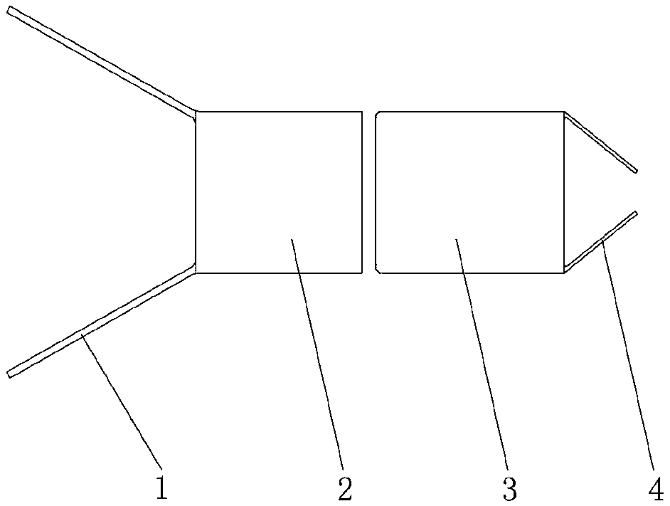
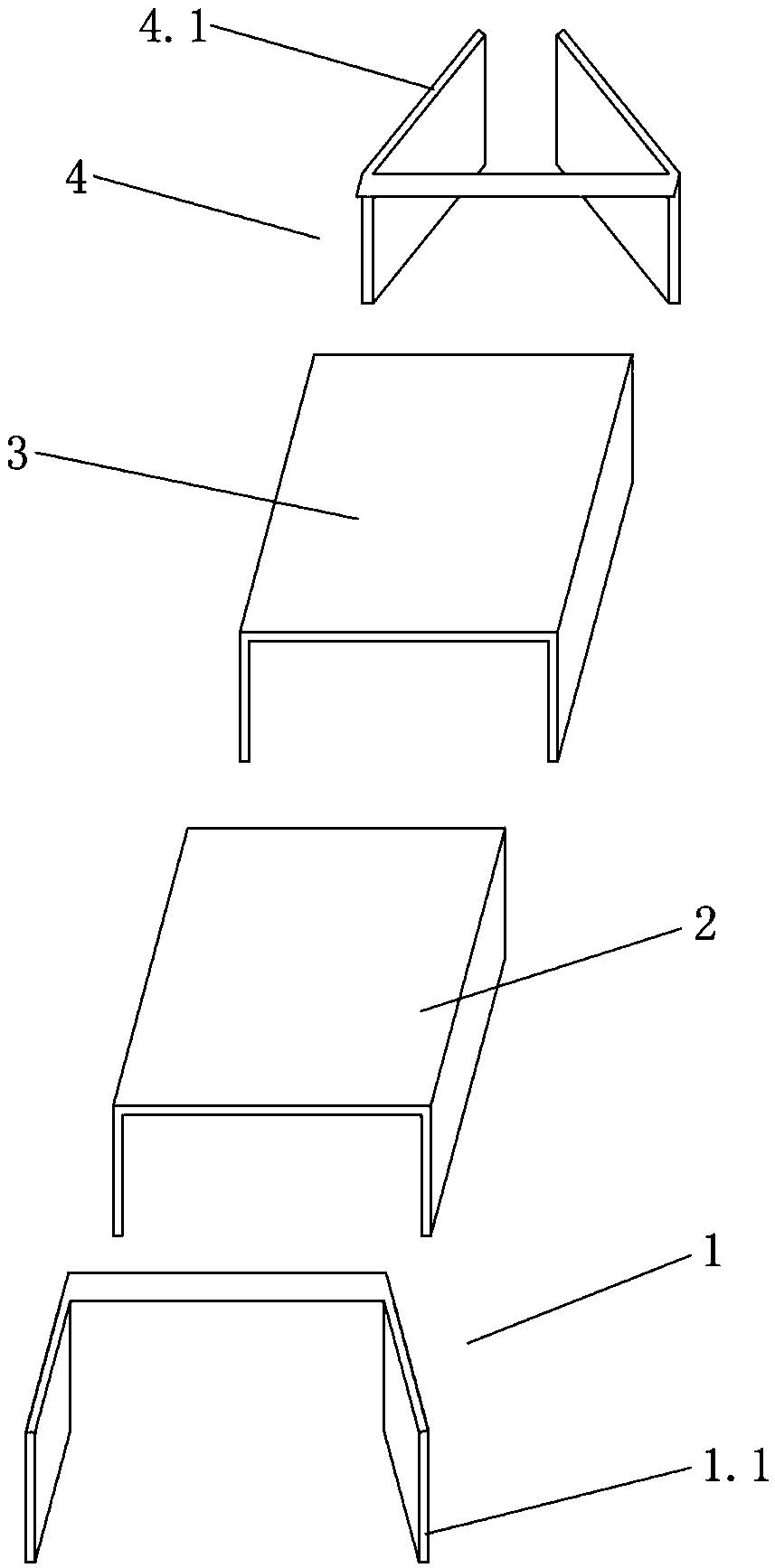
[0012] Such as figure 1 As shown, the cutting guide device is composed of feed chute 1, front chute 2, rear chute 3 and discharge chute 4.

[0013] Such as figure 2 As shown, the feeding trough 1 has two guide plates 1.1, and the angle between the guide plates 1.1 is 130 degrees. The front groove 2 and the rear groove 3 have the same structure and the same length, and both are made of channel steel. There is a gap between the butt ends of the front groove 2 and the ...


PUM

PropertyMeasurementUnit
Angleaaaaaaaaaa
Angleaaaaaaaaaa

Abstract

The invention discloses a cutting guiding device which comprises a feeding groove, a front groove, a rear groove and a discharging groove, wherein the feeding groove is provided with two guiding plates stretching outwards; the front groove is in butt joint with the rear groove through a clearance; and the discharging groove is provided with two clamping plates closing inwards. Under the guiding and positioning function of the front groove and the rear groove, the cut-off length of a workpiece is precise, the workpiece is prevented from deviating from an operating rail due to inertia, the operating continuity is high and the production efficiency is improved.

Description

technical field [0001] The invention belongs to cutting auxiliary equipment, in particular to a cutting guide device. Background technique [0002] The existing cutting machine or punching machine needs to manually push and pull the workpiece to reach the station when cutting the workpiece. Inertial impact force will be generated on the workpiece, causing the workpiece to deviate and fly out of the working track. Contents of the invention [0003] The technical problem to be solved by the invention is to provide a high-precision and stable cutting guide device. [0004] In order to solve the above-mentioned technical problems, the technical solution adopted in the present invention is: a cutting guide device, including a feed trough, a front trough, a rear trough and a discharge chute; plate; the front groove and the rear groove are butted in a gap; the discharge groove has two splints closed inward. [0005] Further, the included angle of the guide plate is 120-140 deg...

Claims


Application Information

Patent Timeline
IPC IPC(8): B26D7/08
CPCB26D7/08B26D2007/082
Inventor 宋绍亮宋建华何金
Owner FOSHAN MEIRUN RUBBER TECH DEV CO LTD
Why Eureka
Try Eureka