Split type rotational molding machine

A rotomolding machine, split-type technology, applied in the direction of coating, etc., to achieve the effect of reducing the overall space, reducing the difficulty of installation, and improving the stability of operation

Inactive Publication Date: 2018-11-23
高密市中科容器厂
View PDF0 Cites 0 Cited by
  • Summary
  • Abstract
  • Description
  • Claims
  • Application Information

AI Technical Summary

Problems solved by technology

[0006] For the problems existing in the prior art, the invention provides a split rotomolding machine, which can solve the problem of the movement precision of the traditional moving door and improve the operation stability of the equipment

Method used


Image

  • Split type rotational molding machine
  • Split type rotational molding machine

Examples


Embodiment Construction

[0021] In order to facilitate the understanding of those skilled in the art, the present invention will be further described below in conjunction with the accompanying drawings.

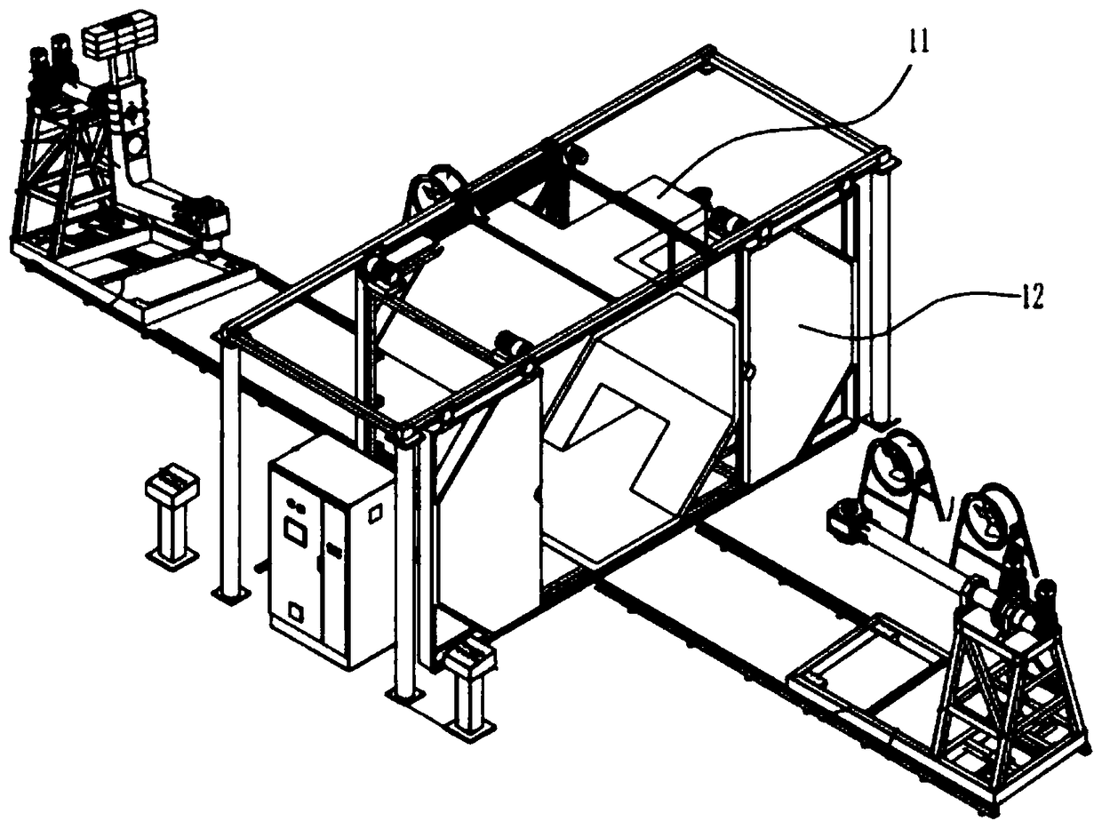
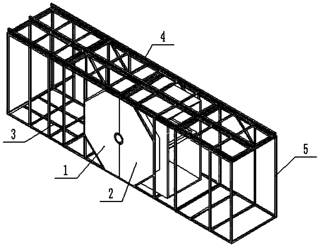
[0022] Such as figure 2 As shown, a split type rotational molding machine comprises a left oven 1, a right oven 2, and a trolley arranged on both sides of the left oven 1 and the right oven 2 and a rotomolding arm on the top of the trolley (the structure is in the figure 2 is shown, please refer to the figure 1 ), the bottom of left oven 1 and / or right oven 2 of the present invention is provided with guide rail 3, and left oven 1 and / or right oven 2 is provided with driving device to drive it to move on guide rail 3, and left oven 1 and right oven 2 are relative When moving and fastening, it forms a sealed cavity with the rotomolding arm. The present invention divides the original oven into two ovens that can be movable and fastened. Since the left oven 1 and the right oven 2 have wider bottoms, c...


PUM


Abstract

The invention discloses a split type rotational molding machine, and belongs to the field of rotational molding machines. The split type rotational molding machine comprises a left drying oven body, aright drying oven body, walking vehicles and rotational molding arms, wherein the walking vehicles are arranged on the two sides of the left drying oven body and the right drying oven body, and the rotational molding arms are arranged at the tops of the walking vehicles; a guide rail is arranged at the bottoms of the left drying oven body and / or the right drying oven body; a driving device for driving the left drying oven body and / or the right drying oven body to move on the guide rail is arranged on the left drying oven body and / or the right drying oven body; and when the left drying oven body and the right drying oven body are relatively and movably fastened, a sealing cavity is defined by the left drying oven body, the right drying oven body and the rotational molding arms. According to the split type rotational molding machine, an original drying oven is divided into two drying oven bodies which can be movably fastened, due to the fact that the bottom of the left drying oven bodyand the bottom of the right drying oven body are relatively wide, a corresponding sliding rail is arranged, so that the problem that the operation of the left drying oven body and the right drying oven body is deflected, jammed and stopped in a movable door can be solved, in addition, the mobile door is removed, the installation difficulty is lowered, and meanwhile, the heat deformation problem ofthe movable door cannot influence the overall sealing performance and sliding of the left drying oven body and the right drying oven body.

Description

technical field [0001] The invention relates to the field of rotational molding machines, in particular to a split type rotational molding machine. Background technique [0002] Rotational molding machine is a kind of mechanical equipment used to manufacture rotational molding products. Its structure is mainly composed of oven, track, walking vehicle and rotational molding working arm. There are two movable doors that can be opened on both sides of the oven. The track is The doors are moved on both sides of the oven, and the trolley moves along a specific track. The rotomolding working arm is installed on the top of the trolley. After the rotomolding mold is installed on the rotomolding working arm, the trolley can move in and out of the oven along a specific track. Thereby, the manufacture of rotationally molded products is carried out. [0003] However, in actual use, especially for large-scale rotomolding machines, the movable doors on both sides of the oven are often de...

Claims


Application Information

Patent Timeline
Patent Type & Authority Applications(China)
IPC IPC(8): B29C41/34B29C41/46
CPCB29C41/34B29C41/46
Inventor 臧群传
Owner 高密市中科容器厂
Why Eureka
Try Eureka