
Polishing machine

A technology of polishing machine and moving mechanism, which is applied in the field of polishing machine, can solve the problems of slow polishing speed, unfavorable personal safety of workers, easy injury to hands, etc., and achieve the effect of protecting internal structure, improving flexibility and automation degree

Pending Publication Date: 2019-11-05
浙江唐风工艺品有限公司
View PDF12 Cites 0 Cited by
  • Summary
  • Abstract
  • Description
  • Claims
  • Application Information

AI Technical Summary

Problems solved by technology

[0002] The polishing machine is a kind of equipment that can polish the surface of the product to make the surface of the product smooth, and the placemat is also a daily necessities that we often come into contact with in our daily life, especially if the placemat made of hard material is not smooth, it will be very difficult. It is easy to hurt hands, but in the existing production process, when polishing the corners of the placemat, the placemat is mainly controlled manually, and the friction between the polishing abrasive cloth roller and the backing plate is used for polishing, and a large amount of dust is generated during polishing , is not conducive to the personal safety of workers, and the polishing speed is relatively slow. Based on this, it is necessary to provide a relatively automatic polishing machine with high polishing efficiency and low dust pollution for the problems existing in the production of placemats.

Method used


Image

  • Polishing machine
  • Polishing machine
  • Polishing machine

Examples


Embodiment

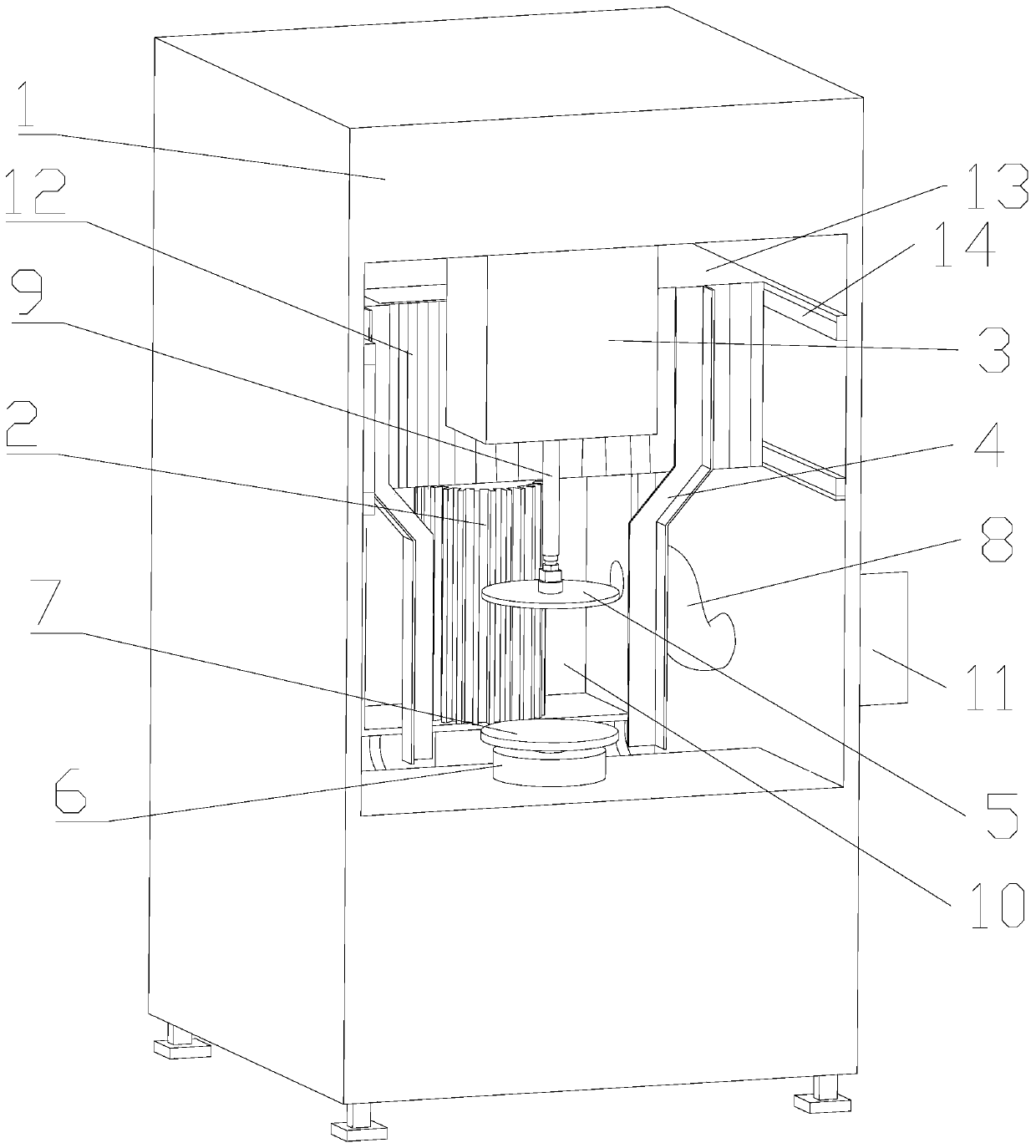
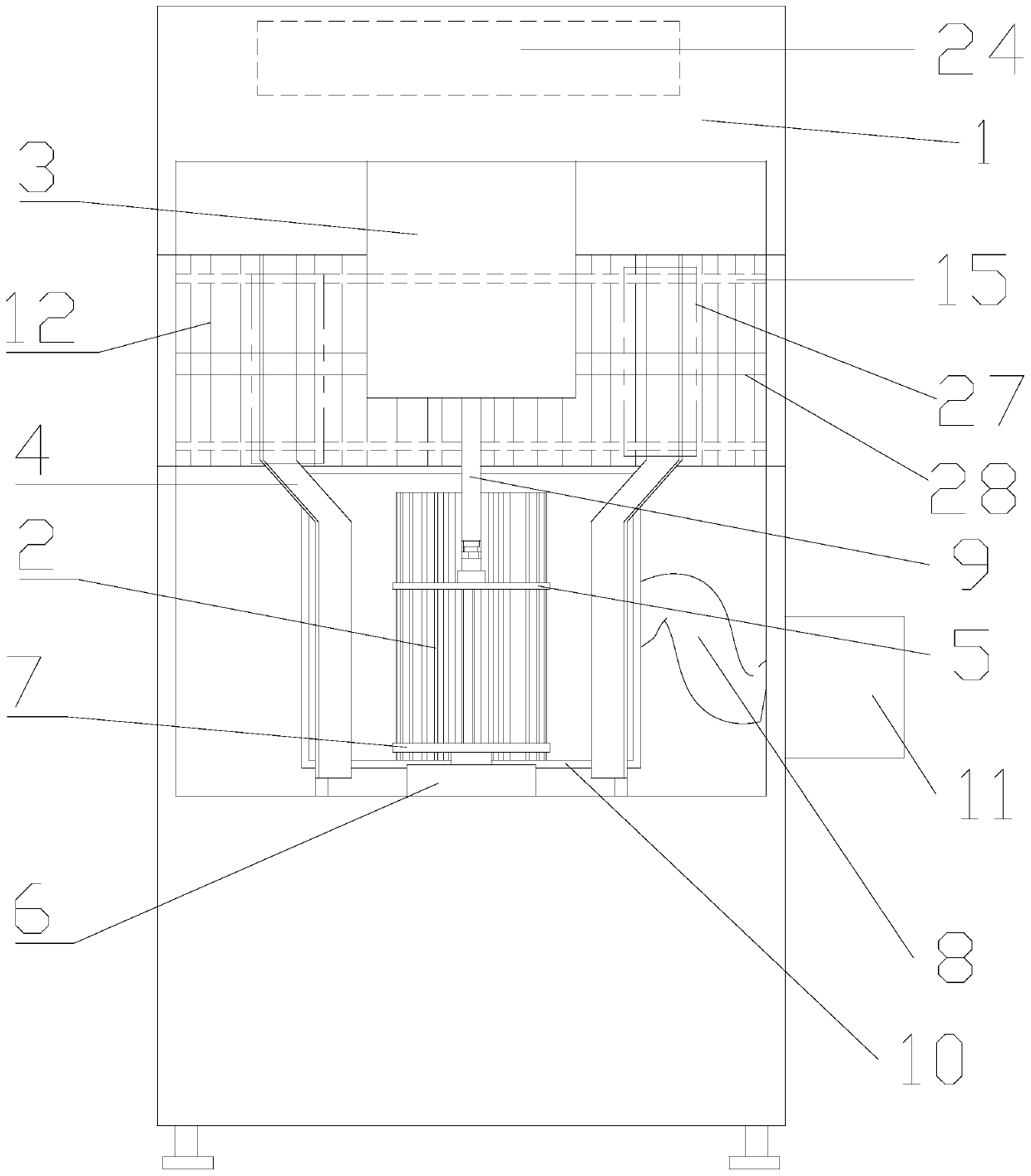
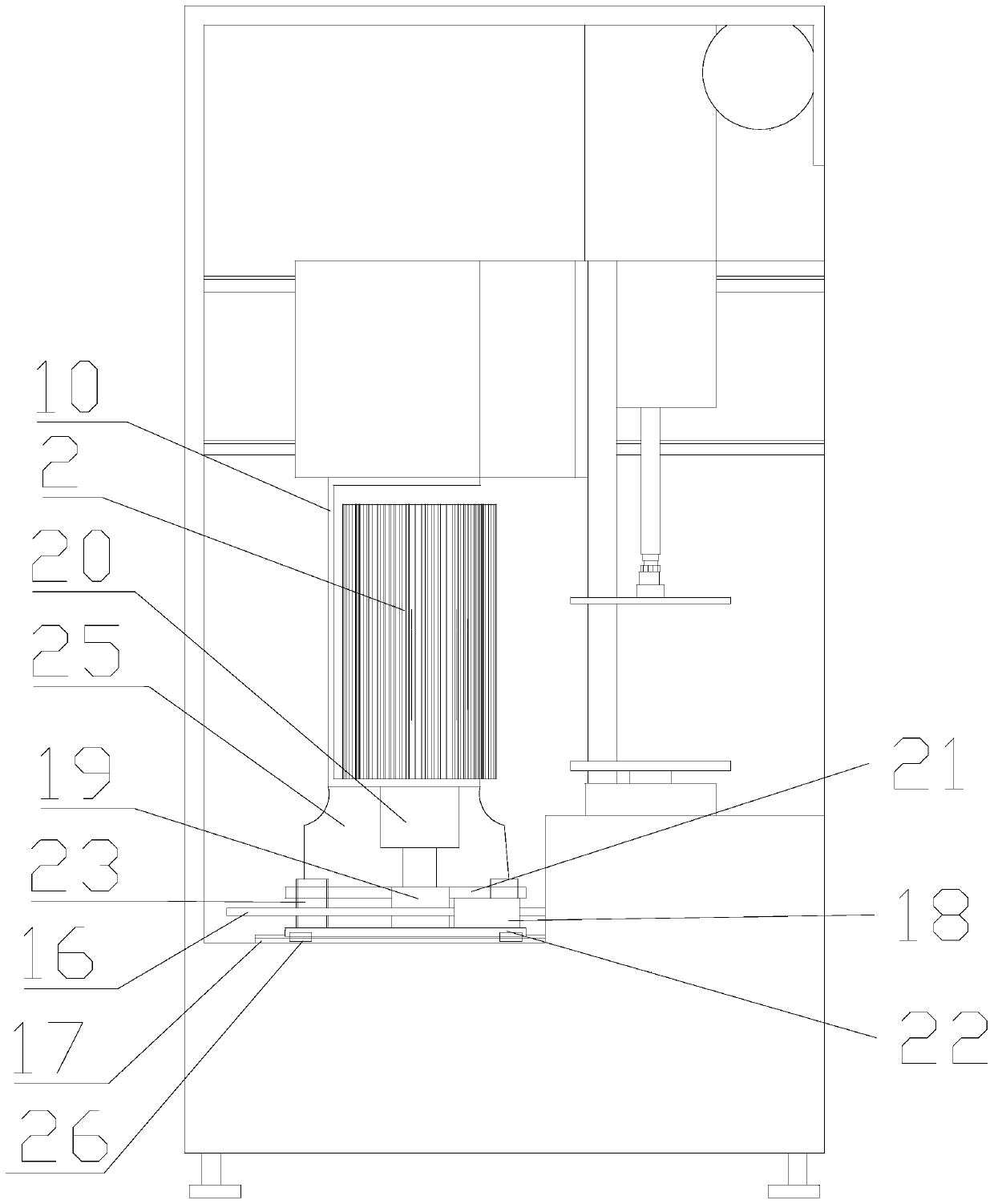
[0025] The invention discloses a polishing machine, which is used for grinding and polishing the corners of placemats. The polishing machine includes a polishing box 1, and the inner cavity of the polishing box 1 is provided with a cylinder 3, a positioning fixture table 13 and a polishing machine. Cavity 10, the bottom of the cylinder 3 is provided with a telescopic shaft 9, the telescopic shaft 9 is provided with a clamping panel 5, a tray 7 is provided below the corresponding position of the clamping panel 5, and a tray 7 is provided below the tray 7 Lifting platform 6 is arranged, and described positioning fixture platform 13 is equipped with moving mechanism, and what moving mechanism adopted promptly is screw drive, specifically comprises transverse guide rail 15, transverse screw mandrel 28, driving motor and traverse block 27, and transverse screw mandrel and The traversing block is slidably matched, and the driving motor is fixedly connected with the horizontal screw r...


PUM


Abstract

The invention relates to a polishing machine. The polishing machine is used for polishing corners of a placemat and comprises a polishing box, wherein an air cylinder, a positioning fixture table anda polishing cavity are arranged in an inner cavity of the polishing box from outside to inside in sequence, a clamping panel is connected with the bottom of the air cylinder through a telescopic shaft, a tray is arranged below the corresponding position of the clamping panel, a lifting platform is arranged below the tray, the positioning fixture table is provided with transverse guide rails and longitudinal guide rails, a positioning fixture is arranged on the transverse guide rails, a folding is arranged between the transverse guide rails and the positioning fixture, a polishing abrasive cloth barrel and a dust exhausting channel are arranged in the polishing cavity, and the polishing abrasive cloth barrel s connected with a rotary motor through a rotating shaft. The polishing machine issimple in product structure, and by means of the design in the scheme, the product is automatically polished, the polishing efficiency and polishing effect of the product are improved, and polishing dust is reduced.

Description

technical field [0001] The invention relates to a grinding device, in particular to a polishing machine for grinding and polishing the corners of a placemat. Background technique [0002] The polishing machine is a kind of equipment that can polish the surface of the product to make the surface of the product smooth, and the placemat is also a daily necessities that we often come into contact with in our daily life, especially if the placemat made of hard material is not smooth, it will be very difficult. It is easy to hurt hands, but in the existing production process, when polishing the corners of the placemat, the placemat is mainly controlled manually, and the friction between the polishing abrasive cloth roller and the backing plate is used for polishing, and a large amount of dust is generated during polishing , It is not conducive to the personal safety of workers, and the polishing speed is relatively slow. Based on this, it is necessary to provide a relatively autom...

Claims


Application Information

Patent Timeline
Patent Type & Authority Applications(China)
IPC IPC(8): B24B29/02B24B41/00B24B41/06B24B47/00B24B47/12B24B47/22B24B55/00B24B55/06F21V33/00
CPCB24B29/02B24B41/06B24B47/00B24B47/22B24B47/12B24B55/06B24B41/00B24B55/00F21V33/00
Inventor 林满华
Owner 浙江唐风工艺品有限公司
Learn More