
Telescopic boom and mobile crane

A telescopic, boom technology used in cranes, transportation and packaging to solve problems such as unfavorable stress spikes

Active Publication Date: 2018-11-23
LIEBHERR WERK EHINGEN
View PDF5 Cites 1 Cited by
  • Summary
  • Abstract
  • Description
  • Claims
  • Application Information

AI Technical Summary

Problems solved by technology

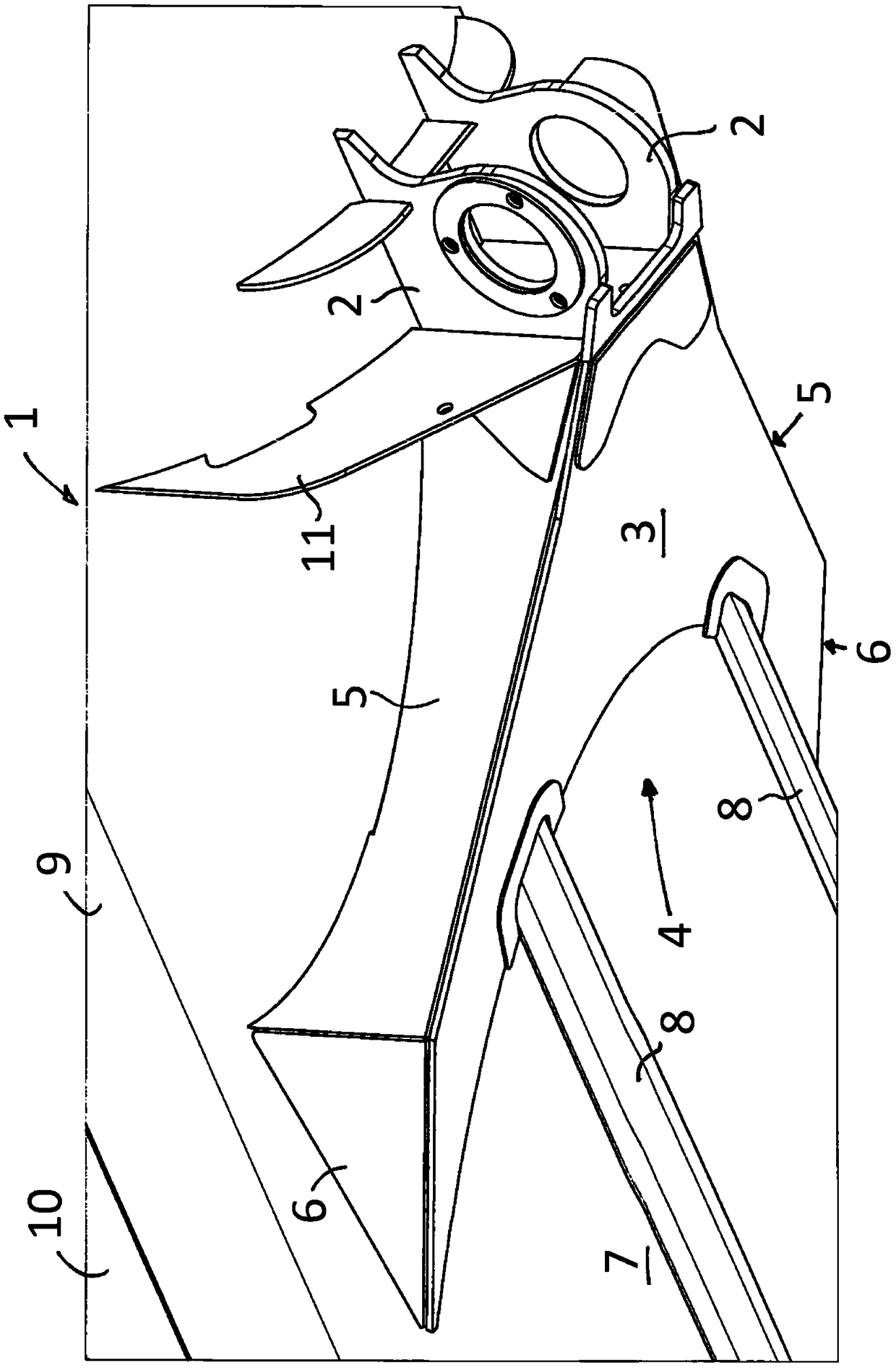
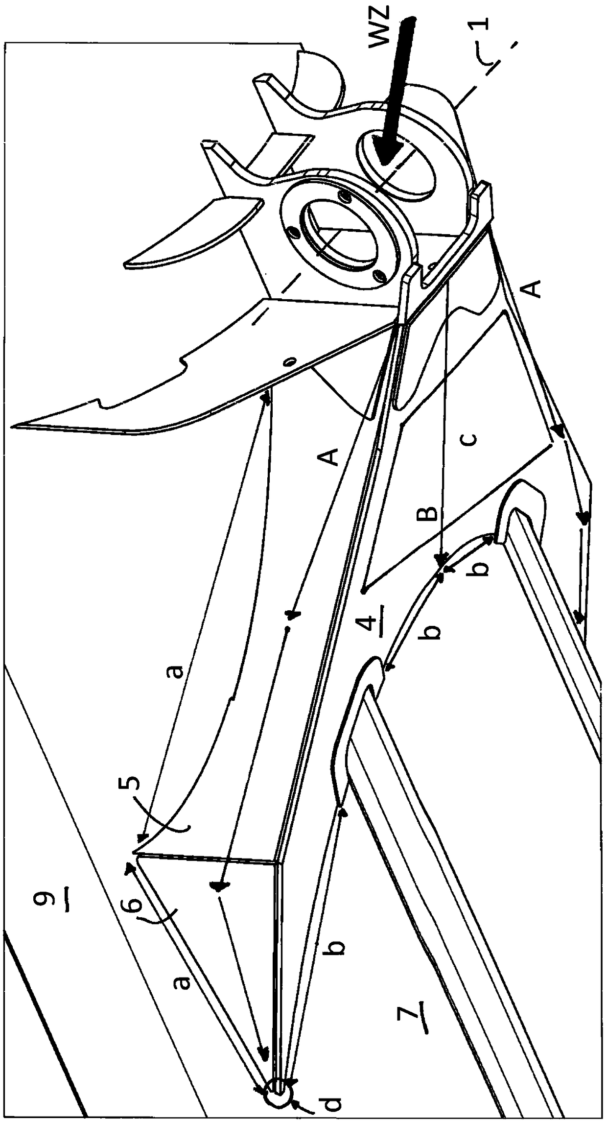
[0007] Furthermore, a further disadvantage of the plate construction shown is due to the fact that the wall element 6 and the cover plate 3 form a sharp point d of the box, which is pressed into the lower housing 7 in a punctiform manner and thus produces unfavorable stresses peak

Method used


Image

  • Telescopic boom and mobile crane
  • Telescopic boom and mobile crane
  • Telescopic boom and mobile crane

Examples


Embodiment Construction

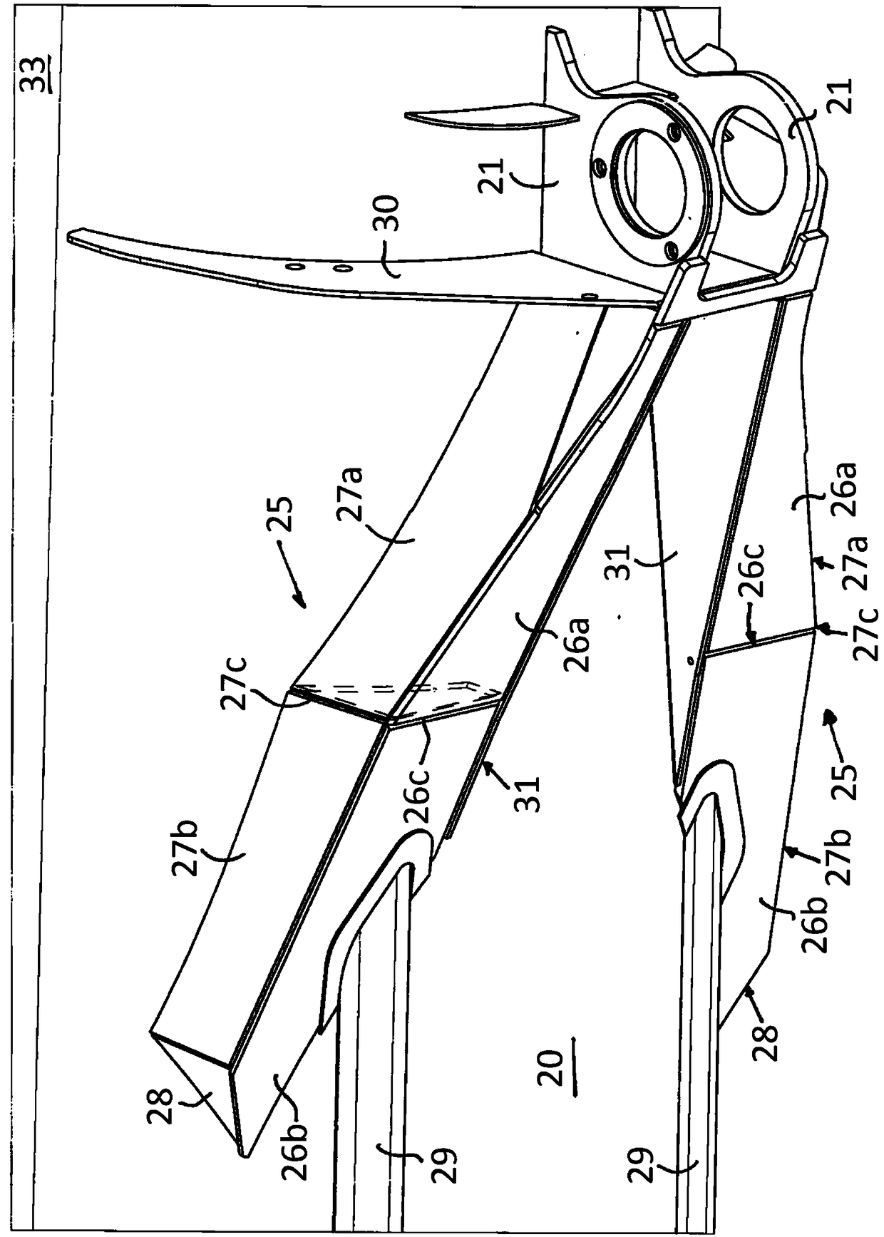
[0029] image 3 and Figure 4 A novel construction of the telescoping boom is now shown. It can be seen that a sub-region of the lower housing 20 of the telescopic boom has a bolt receptacle for coupling a luffing cylinder. To accommodate the bolts of the luffing cylinder, two bolt bearing plates 21 are provided, which have corresponding reinforcing plates. Adjoined to it are two narrow closed board boxes 25 , which are constructed identically to each other. The two boxes 25 each comprise a two-part cover plate with individual elements 26 a , 26 b which are connected to one another via an edge 26 c. The two outer side walls of the box structure 25 are formed in two parts with individual elements 27a, 27b which are in contact with one another via an edge 27c. A closing plate 28 is arranged at the end-side end. The inner side walls 31 of the crate structure are formed in one piece.

[0030] Inside each of the two box-shaped structures 25 there is an inner upright plate 32 ...


PUM


Abstract

The present invention relates to a telescopic boom having a coupling section at whose lower shell at least one luffing cylinder mount, in particular a bolt mount, is centrally provided for fastening at least one luffing cylinder, wherein at least two closed sheet metal box structures for the load transmission from the luffing cylinder mount into the structure of the telescopic boom are provided atthe support metal sheets of the luffing cylinder mount.

Description

technical field [0001] The invention relates to a telescopic boom for cranes, in particular for mobile cranes, on the lower shell of which telescopic boom is centrally arranged at least one luffing cylinder receptacle, in particular is a bolt receptacle for fixing at least one luffing cylinder. Background technique [0002] Many crane models use a centrally arranged luffing cylinder which can be bolted to the coupling of the telescoping boom via a bolt receptacle. The load is thus transferred via the bolt receptacle into the lower shell of the boom jig, which requires a special plate construction of the joint support. figure 1 The view of shows the conventional technical solution of the prior art luffing cylinder housing. Two hinged bearing plates 2 are shown, which are welded together with the lower shell 7 of the coupling 1 . Attached to the carrier plate 2 is a relatively wide and closed plate structure 4 consisting of a cover plate 3 and two two-part side walls with i...

Claims


Application Information

Patent Timeline
Patent Type & Authority Applications(China)
IPC IPC(8): B66C23/687B66C23/82
CPCB66C23/701B66C23/82B66C23/64B66C2700/0357
Inventor S·布佐斯卡M·赫尔博格
Owner LIEBHERR WERK EHINGEN
Learn More