
concrete vibrating device

A vibrating device and concrete technology, which is applied in the processing of building materials, construction, building construction, etc., can solve the problems of inability to reduce noise, high noise, and environmental impact with flat vibrators, so as to reduce the external transmission of vibration and reduce the impact on the environment. Noise, the effect of meeting the needs of use

Active Publication Date: 2020-12-04
GUANGZHOU CITY CONSTR COLLEGE
View PDF2 Cites 2 Cited by
  • Summary
  • Abstract
  • Description
  • Claims
  • Application Information

AI Technical Summary

Problems solved by technology

Usually, the method that people adopt is vibration exhaust method, promptly utilizes mechanical plate vibrator to vibrate inside and on the surface of the concrete being poured, so as to realize exhausting and enriching the inside of the concrete, but the existing plate vibrator works The noise generated during the operation is too large, which has a great impact on the surrounding environment, and only the sound insulation layer cannot fully reduce the noise of the plate vibrator

Method used


Image

  • concrete vibrating device
  • concrete vibrating device

Examples


Embodiment Construction

[0016] The present invention is further described below in conjunction with embodiment.

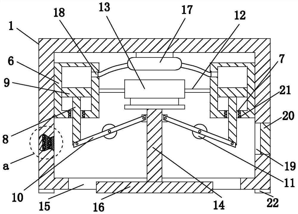
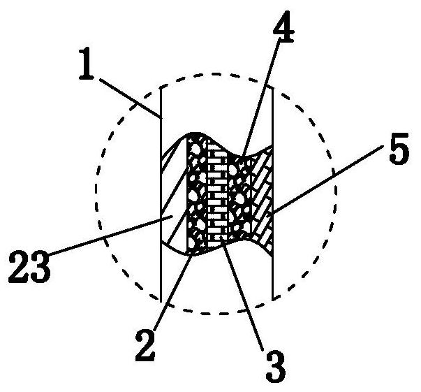
[0017] like figure 1 , figure 2 A concrete vibrating device is shown, which includes a sound-insulating shell 1. The sound-insulating shell 1 is in the shape of a square shell. The sound-insulating shell 1 sequentially includes an outer layer 23, a first sound-insulating felt layer 2, and a light steel keel layer from outside to inside. 3. The second sound-insulating felt layer 4, gypsum board 5, and light steel keel layer 3 have the characteristics of light weight and high strength, which can ensure the strength of the sound-insulating shell 1, but the weight is not too heavy. The four sides and the upper end of the soundproof shell 1 are all closed, and the lower end is provided with a vibrating port 15 .

[0018] There are two left and right cylinders 6 inside the soundproof shell 1, and the two cylinders 6 are respectively fixed on the innermost gypsum board 5 of the soundproof she...


PUM


Abstract

The invention discloses a concrete vibration device. The concrete vibration device comprises a sound-proof shell which comprises an outer layer, a first sound-proof felt layer, a lightgage steel joistlayer, a second sound-proof felt layer and a gypsum board from outside to inside in sequence, a vibration opening is formed in the lower end of the sound-proof shell, a left cylinder and a right cylinder are arranged in the sound-proof shell, and first round holes are formed in the middles of the lower ends of the cylinders. Pistons are arranged in the cylinders, the lower ends of the pistons areconnected with piston rods, an air bag is fixedly installed in the sound-proof shell, and the air bag is communicated into the left and right cylinders. A plate vibrator is installed in the middle inthe sound-proof shell, the vibration output end on the lower side of the plate vibrator is fixedly provided with a vertical column, and the lower end of the vertical column is fixedly provided with apress plate. Oblique rods are arranged between the vertical column and the piston rods respectively, the middles of the oblique rods are hinged to the sound-proof shell, one end of each oblique rod is hinged to the vertical column, the other ends of the oblique rods are hinged to the lower ends of the piston rods, and an observation window is formed in the side wall of the sound-proof shell. Theconcrete vibration device is low in noise and small in shell vibration.

Description

technical field [0001] The invention relates to the technical field of construction equipment, in particular to a concrete vibrating device. Background technique [0002] When using concrete to pour the pillars, beams and frame structures of buildings, in order to eliminate the air trapped in the concrete and meet the requirements of the construction standard quality, it is necessary to exhaust and enrich the concrete being poured. Usually, the method that people adopt is vibration exhaust method, promptly utilizes mechanical plate vibrator to vibrate inside and on the surface of the concrete being poured, so as to realize exhausting and enriching the inside of the concrete, but the existing plate vibrator works The noise generated during the vibration is too large, which has a great impact on the surrounding environment, and only the sound insulation layer cannot fully reduce the noise of the flat vibrator. [0003] Especially for the prefabricated buildings that the count...

Claims


Application Information

Patent Timeline
Patent Type & Authority Patents(China)
IPC IPC(8): E04G21/06
CPCE04G21/066
Inventor 印宝权鄢维峰鲁周静
Owner GUANGZHOU CITY CONSTR COLLEGE
Learn More