
Water conveying device for high floor

A high-floor, water-delivery technology, applied in the direction of liquid variable capacity machinery, pump control, machine/engine, etc., can solve the problems of limited conveying capacity, limited water accumulation and dust in pumps, etc., to reduce multiple conveying, strong practicability, effect of change

Inactive Publication Date: 2018-11-23
陈晓茜 +2
View PDF6 Cites 8 Cited by
  • Summary
  • Abstract
  • Description
  • Claims
  • Application Information

AI Technical Summary

Problems solved by technology

[0002] At present, when building a house, especially a high-rise house, in order to provide the water source used by each household, it is necessary to send water, and in order to transfer the low-level water source to the high-level, a water delivery device will be used. The general water delivery device will A water pump is used, but due to the limited accumulation of water and dust in the water pump, and the general water pump uses a turbine for water delivery. Since the turbine needs external air for pressure delivery, its maximum pumping capacity is the pressure of atmospheric pressure, resulting in a limited delivery capacity.

Method used


Image

  • Water conveying device for high floor
  • Water conveying device for high floor
  • Water conveying device for high floor

Examples


Embodiment Construction

[0028] The technical solutions in the embodiments of the present invention will be clearly and completely described below in conjunction with the accompanying drawings in the embodiments of the present invention. Obviously, the described embodiments are only a part of the embodiments of the present invention, rather than all the embodiments. Based on the embodiments of the present invention, all other embodiments obtained by those of ordinary skill in the art without creative work shall fall within the protection scope of the present invention.

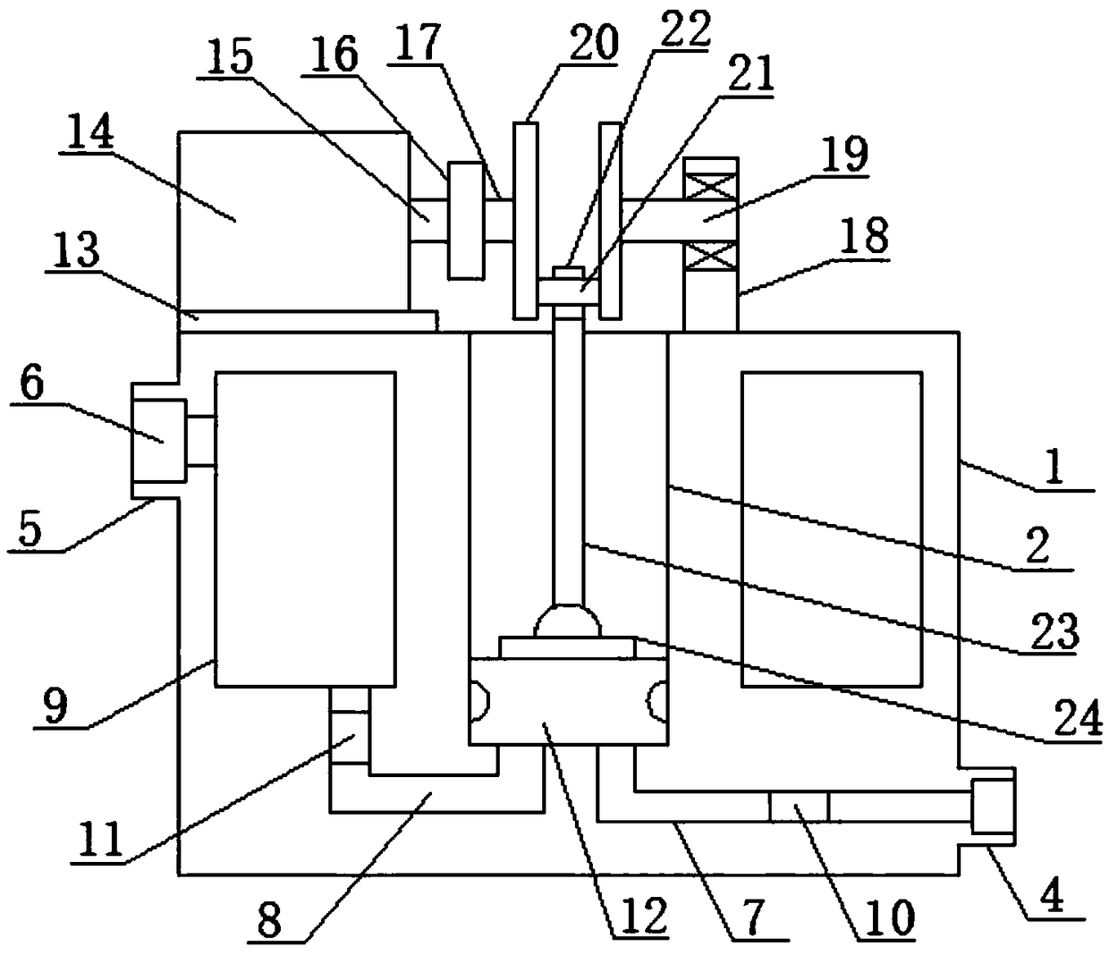
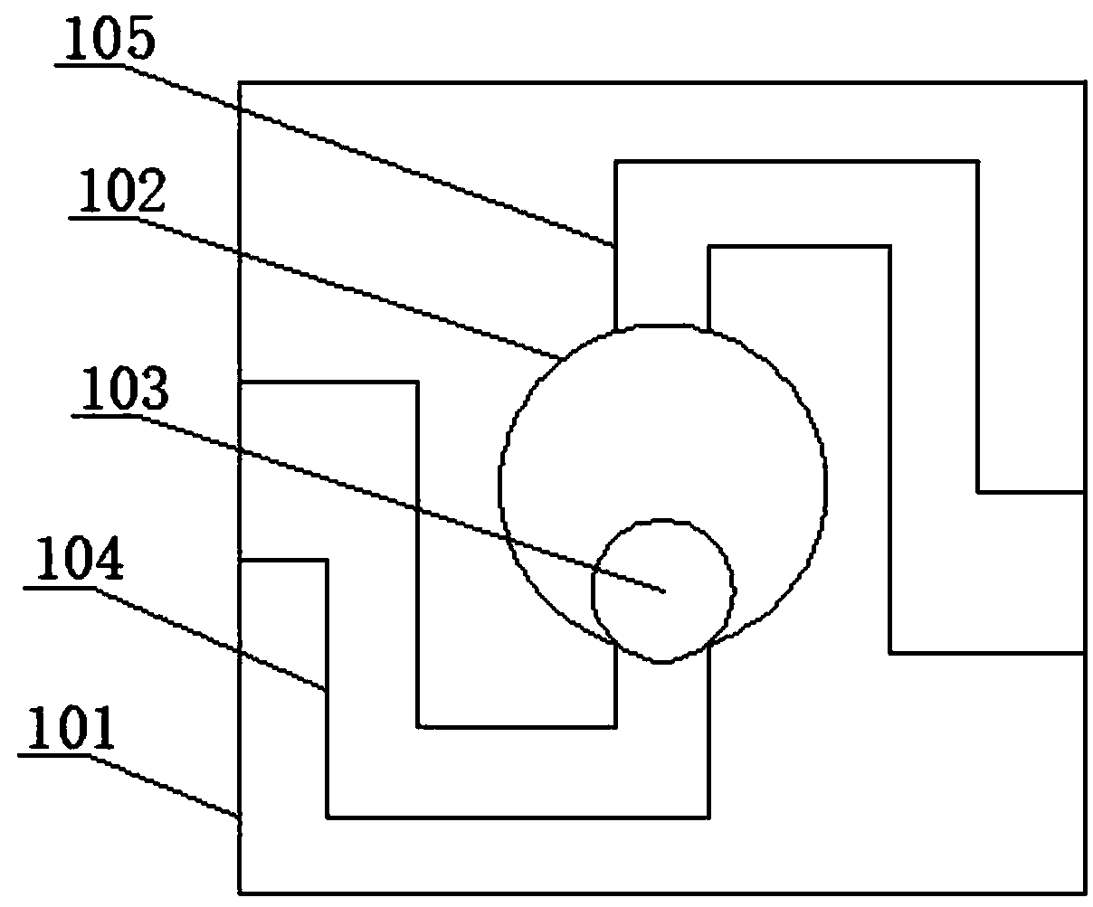
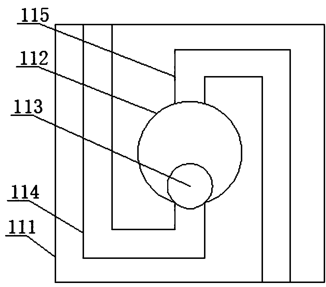
[0029] See figure 1 , An embodiment provided by the present invention includes a main hollow shell 1, an open-air liquid compression space 2 is provided in the center of the main hollow shell 1, and the inside of the main hollow shell 1 is located in the liquid compression space 2 An annular liquid reserve space 9 is provided on the periphery, a main drain connection pipe port 4 is provided at the bottom of the side of the main hollow hou...


PUM


Abstract

The invention discloses a water conveying device for a high floor. The water conveying device comprises a main hollow housing. According to the water conveying device disclosed by the invention, a turbine element is changed to be in a longitudinal direction and realizes controllable pressure conveying, so the water conveying efficiency is obviously improved, water can be conveyed to a higher distance, repeated conveying is reduced, and high practicability is realized; moreover, the water conveying device comprises a first large-size pressure liquid one-way flowing control mechanism which can realize that the liquid enters a liquid compression position in one direction from a water storage position; besides, the water conveying device comprises a second large-size pressure liquid one-way flowing control mechanism; by utilizing the characteristics of the first large-size pressure liquid one-way flowing control mechanism and the second large-size pressure liquid one-way flowing control mechanism, a discharging effect is achieved; moreover, the water conveying device comprises a maximum rotation force control and protection mechanism and a universal rotating connecting mechanism, wherein the universal rotating connecting mechanism can be used for connecting a longitudinal moving component and a component which moves in a rotation angle, thus the movement direction of the componentis changed, and a liquid compression driving effect is achieved.

Description

Technical field [0001] The invention relates to the technical field of building construction, in particular to a water delivery device for high floors. Background technique [0002] At present, in the construction of houses, especially high-floor houses, in order to provide the water source used by each household, water delivery is required. In order to deliver the low-level water source to the high-level, water delivery devices are used. General water delivery devices will Pumps are used, but due to the limited accumulation of water and dust in the pumps, the general pumps use turbines for water source transportation. Because the turbines need external air for pressure transmission, their maximum pumping capacity is atmospheric pressure, resulting in limited delivery capacity. Summary of the invention [0003] The purpose of the present invention is to provide a high-floor water supply device to solve the above-mentioned background art problems. [0004] In order to achieve the ab...

Claims


Application Information

Patent Timeline
Patent Type & Authority Applications(China)
IPC IPC(8): F04B17/03F04B49/22
CPCF04B17/03F04B49/22
Inventor 陈晓茜高峰孟淑焕
Owner 陈晓茜
Learn More