
Rotor compressor and temperature regulating device

Pending Publication Date: 2018-11-23
ZHUHAI LANDA COMPRESSOR +1
View PDF3 Cites 0 Cited by
  • Summary
  • Abstract
  • Description
  • Claims
  • Application Information

AI Technical Summary

Problems solved by technology

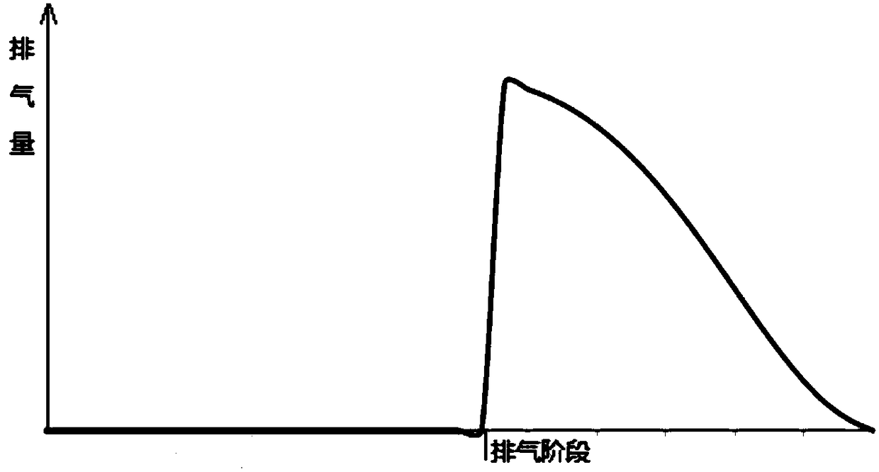
[0006] Therefore, the technical problem to be solved by the present invention is to overcome the defect that the exhaust port in the prior art cannot be set according to the change of the displacement, thereby providing a rotary compressor and a temperature regulating device

Method used


Image

  • Rotor compressor and temperature regulating device
  • Rotor compressor and temperature regulating device
  • Rotor compressor and temperature regulating device

Examples


Embodiment Construction

[0038] The technical solutions of the present invention will be clearly and completely described below in conjunction with the accompanying drawings.

[0039] The invention describes a temperature regulating device, such as an air conditioner or a refrigerator, which includes a rotor compressor.

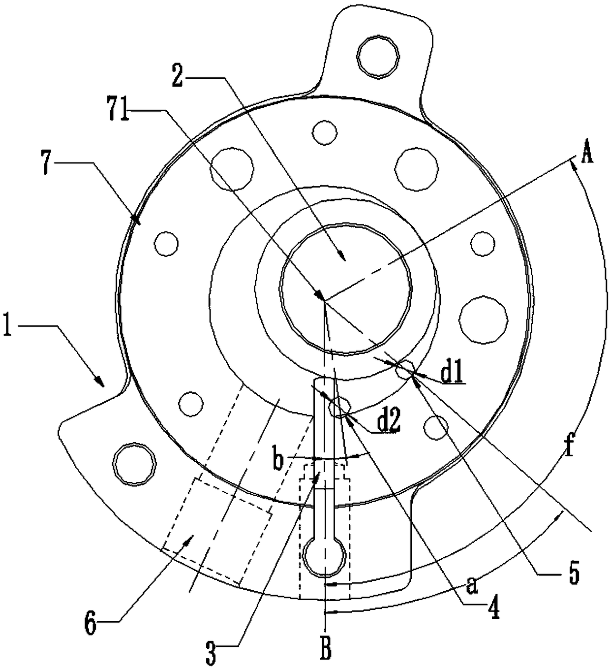
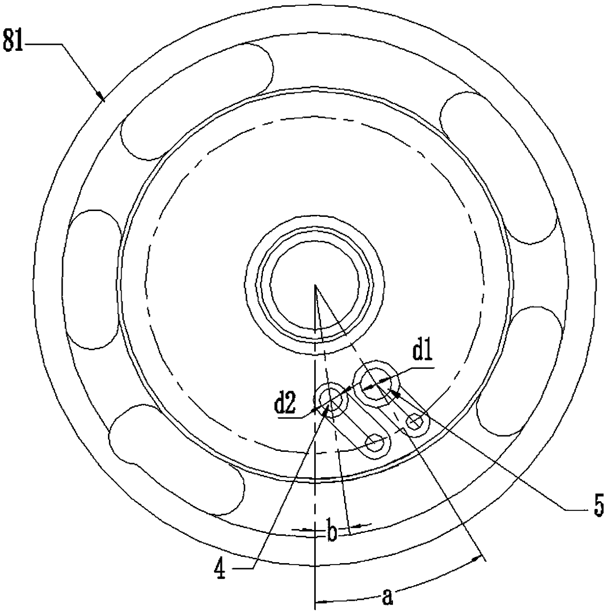
[0040] Such as figure 2 As shown, a rotary compressor of the present invention includes a pump body 1 , a rotor 2 and a sliding vane 3 . Among them, the pump body 1 is a cylindrical sealed cavity inside; the rotor 2 is a cam whose rotation center is coaxial with the cavity (that is, an eccentric rotor), and the cam and the cavity are always in tangential contact during rotation; the slide plate 3 Slidingly arranged on the pump body 1, it is always in contact with the rotor 2 under the action of the biasing force. The pump body 1 is also provided with a main exhaust port 4, an auxiliary exhaust port 5 and a suction port 6, wherein the main exhaust port 4 is arranged on the pump bod...


PUM


Abstract

The invention discloses a temperature regulating device and a rotor compressor. The rotor compressor comprises a pump body, a rotor, a slip sheet, a main exhaust hole and an intake hole, wherein the pump body is internally provided with a cylindrical sealing cavity; the rotor is a cam, the center of rotation of which is coaxial with the cavity, the cam and the cavity are always in tangential contact during the process of rotating; the sliding piece is arranged on the pump body in a slidable manner, and is always in contact with the rotor under the action of biasing pressure; the main exhaust hole is positioned close to the slip sheet and on the pump body and is arranged in an exhaust section corresponding to the cavity; the intake hole is formed in the pump body and corresponds to the compression section of the cavity; and the pump body is further provided with at least one auxiliary exhaust hole corresponding to the exhaust section of the cavity, the auxiliary exhaust hole is away from the slip sheet and is separated from the main exhaust hole with a turning angle in the circumferential direction.

Description

technical field [0001] The invention relates to the technical field of compressor equipment, in particular to a rotor compressor and a temperature regulating device. Background technique [0002] An exhaust structure of a vane compressor is disclosed in the prior art, the exhaust structure of the vane compressor includes: an exhaust hole, the exhaust hole is arranged on the flange of the vane compressor, and It communicates with the compression chamber of the cylinder of the vane compressor; the diversion channel is arranged on the flange and runs through the flange; the exhaust channel is arranged on the eccentric circle of the vane compressor, and the exhaust channel is arranged on the eccentric circle of the vane compressor. The gas channel is used to communicate with the compression cavity and the guide channel with the rotation of the eccentric circle. There are multiple exhaust holes, and multiple exhaust holes and guide channels are arranged sequentially along the di...

Claims


Application Information

Patent Timeline
Patent Type & Authority Applications(China)
IPC IPC(8): F04C18/356F04C29/12
CPCF04C18/3566F04C29/12
Inventor 蓝榕江雷卫东廖熠高永红陈恩峥蓝国嘉
Owner ZHUHAI LANDA COMPRESSOR
Learn More