Supercharge Your Innovation With Domain-Expert AI Agents!

Electromechanical equipment mounting seat

A technology for electromechanical equipment and mounting seats, which is applied in the direction of mechanical equipment, supporting machines, engine frames, etc., can solve the problems of simple structure, easy to be affected by ground moisture, and affect the normal use of equipment, and achieve the effect of novel structure and convenient use

Inactive Publication Date: 2018-11-23
安徽致精机电科技有限公司
View PDF8 Cites 0 Cited by
  • Summary
  • Abstract
  • Description
  • Claims
  • Application Information

AI Technical Summary

Problems solved by technology

[0002] Electromechanical equipment generally refers to machinery, electrical appliances, and electrical automation equipment. In construction, it refers to the collective name of machinery and pipeline equipment other than geotechnical, carpentry, steel bars, and muddy water. When installing electromechanical equipment, it is generally installed directly on the ground. In general, the bottom of the electromechanical equipment is directly in contact with the ground, which is easily affected by the moisture of the ground, which affects the normal use of the equipment. In order to avoid this situation, there are currently some electromechanical equipment mounting seats on the market, but the existing mounting seats have simple structures. , in the installation process of electromechanical equipment, there is a problem that it is difficult to level and align, which brings some troubles to the installation of the equipment and needs to be improved

Method used


Image

  • Electromechanical equipment mounting seat
  • Electromechanical equipment mounting seat
  • Electromechanical equipment mounting seat

Examples


Embodiment Construction

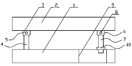
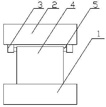
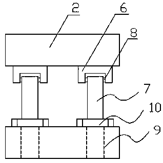
[0013] like Figure 1-3 As shown, the present invention discloses a mounting seat for electromechanical equipment, including: a base 1, a mounting plate 2, a fixing block 3, a support plate 4, a left rotating shaft 5, an adapter block 6, a screw rod 7, a right rotating shaft 8, and a vertical groove 9 , limit nut 10, the mounting plate 2 is placed directly above the base 1, and a fixed block 3 is respectively installed on the left side and the inner side of the lower end surface of the mounting plate 2, and the support plate 4 is vertically fixed on the left side of the upper end surface of the base 1 , and the upper parts of the inner and outer ends of the support plate 4 are fixedly connected with a left rotating shaft 5, the other end of the left rotating shaft 5 not connected with the support plate 4 is rotationally connected with the fixed block 3 on the same side through a bearing, the mounting plate 2 The right side of the lower end surface is fixedly connected with two...


PUM


Abstract

The invention discloses an electromechanical equipment mounting seat. The electromechanical equipment mounting seat comprises a base, a mounting plate, fixing blocks, a supporting plate, left rotatingshafts, rotating connection blocks, threaded rods, right rotating shafts, vertical grooves and limiting nuts, wherein the inner and outer sides of the left edge of the lower end face of the mountingplate are both provided with one fixing block, the supporting plate is vertically and fixedly connected to the left side of the upper end face of the base, the upper portions of the inner and outer end faces of the supporting plate are both fixedly connected with one left rotating shaft, the other ends, not connected with the supporting plate, of the left rotating shafts are rotationally connectedwith the fixing blocks at the same side through bearings, the right side of the lower end face, relative to the fixing blocks, of the mounting plate is fixedly connected with the two rotating connection blocks, each rotating connection block is internally and rotationally provided with one threaded rod, the upper portion of the peripheral surface of each threaded rod is fixedly connected with thetwo right rotating shafts, the threaded rods are rotationally connected with the rotating connection blocks through the right rotating shafts, the portions, corresponding to the threaded rods, of theright portion of the base are provided with the vertical grooves, the lower ends of the threaded rods stretch into the corresponding vertical grooves, and the threaded rods are in threaded connectionwith the limiting nuts. The electromechanical equipment mounting seat has the advantages that the structure is novel, and the use is convenient.

Description

technical field [0001] The invention relates to an electromechanical equipment installation seat, which is applied in the technical field of electromechanical equipment installation. Background technique [0002] Electromechanical equipment generally refers to machinery, electrical appliances, and electrical automation equipment. In construction, it refers to the collective name of machinery and pipeline equipment other than geotechnical, carpentry, steel bars, and muddy water. When installing electromechanical equipment, it is generally installed directly on the ground. In general, the bottom of the electromechanical equipment is directly in contact with the ground, which is easily affected by the moisture of the ground, which affects the normal use of the equipment. In order to avoid this situation, there are currently some electromechanical equipment mounting seats on the market, but the existing mounting seats have simple structures. , in the installation process of elec...

Claims


Application Information

Patent Timeline
IPC IPC(8): F16M1/00
CPCF16M1/00
Inventor 吕中杰
Owner 安徽致精机电科技有限公司
Features
  • R&D
  • Intellectual Property
  • Life Sciences
  • Materials
  • Tech Scout
  • Unparalleled Data Quality
  • Higher Quality Content
  • 60% Fewer Hallucinations
Learn More