Stabilization of Opening Angle of Micromirrors Controlled by Current Driving

A driving control and mirror technology, applied in optical components, instruments, optics, etc., can solve the problem that the current mirror driving technology does not provide an opening angle, etc.

Active Publication Date: 2022-03-25
STMICROELECTRONICS SRL
View PDF6 Cites 0 Cited by
  • Summary
  • Abstract
  • Description
  • Claims
  • Application Information

AI Technical Summary

Problems solved by technology

However, the current mirror drive technique may not provide a constant opening angle when the operating conditions or characteristics of the circuitry change

Method used


Image

  • Stabilization of Opening Angle of Micromirrors Controlled by Current Driving
  • Stabilization of Opening Angle of Micromirrors Controlled by Current Driving
  • Stabilization of Opening Angle of Micromirrors Controlled by Current Driving

Examples


Embodiment Construction

[0017] One or more embodiments of the present disclosure will be described below. These described embodiments are merely examples of the presently disclosed technology. Additionally, in an effort to provide a concise description, all features of an actual implementation may not be described in the specification.

[0018] When introducing elements of various embodiments of the present disclosure, the articles "a," "an," and "the" are intended to mean that there are one or more of the elements. The terms "comprising", "comprising" and "having" are intended to be inclusive and mean that there may be additional elements other than the listed elements. Additionally, it should be understood that references to "one embodiment" or "an embodiment" of the present disclosure are not intended to be interpreted as excluding the existence of other embodiments that also incorporate the recited features.

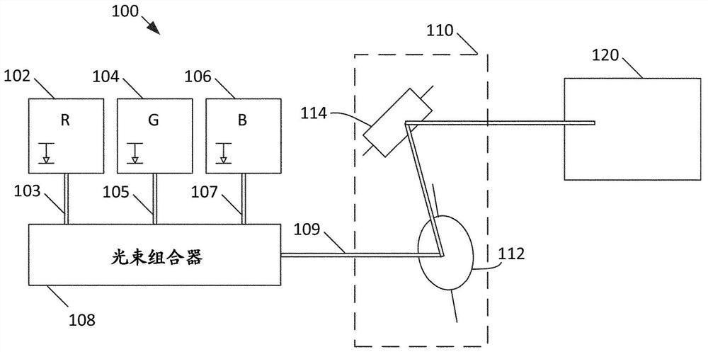
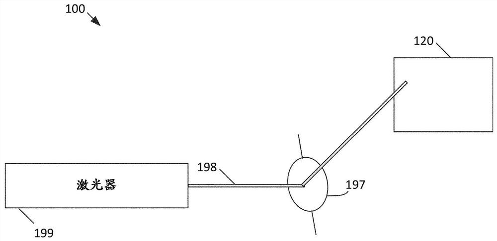
[0019] Here is the first reference Figure 1A A laser scanning device 100 is describe...


PUM


Abstract

Embodiments of the present disclosure relate to stabilization of opening angles of micromirrors controlled by current driving. An electronic device disclosed herein includes a mirror controller configured to generate a drive control signal, and a drive circuit configured to generate a drive signal for a movable mirror based on the drive control signal. The sensing circuit is configured to sense the drive signal. The mirror controller is further configured to adjust the drive control signal based on the sensed drive signal.

Description

technical field [0001] The present disclosure relates generally to the actuation of micromirrors for image scanning, and more particularly to methods of actuating the micromirrors to help maintain a temporally consistent opening angle. Background technique [0002] Certain devices such as wafer defect scanners, laser printers, document scanners, projectors, etc. employ a collimated laser beam that sweeps a flat surface in a straight or curved path. These devices employ tilted mirrors to deflect the beam to perform scanning. These tilting mirrors may be or may include microelectromechanical systems ("MEMS") devices. Actuation of mirrors used in MEMS devices (referred to herein as MEMS mirrors) can be by electromagnetic, electrostatic, piezoelectric, and pyroelectric effects, depending on the application. [0003] A common type of MEMS mirror includes a stator and a rotor, where the rotor or structures carried by the rotor are reflective. Driving the stator and / or rotor wit...

Claims


Application Information

Patent Timeline
Patent Type & Authority Patents(China)
IPC IPC(8): G02B26/08
CPCG02B26/0833G02B26/085G02B26/105G02B26/101
Inventor E·哈兰
Owner STMICROELECTRONICS SRL
Why Eureka
Try Eureka