
Reflective liquid crystal display panel, its manufacturing method and display device

A liquid crystal display panel, reflective technology, used in instruments, light guides, optics, etc., can solve problems such as low ratio, and achieve the effects of improving contrast, eliminating escape, and avoiding light escape

Active Publication Date: 2021-02-02
BOE TECH GRP CO LTD +1
View PDF9 Cites 0 Cited by
  • Summary
  • Abstract
  • Description
  • Claims
  • Application Information

AI Technical Summary

Problems solved by technology

For the escaping light, in the non-reflective LCD panel, a reflective sheet will be added on the side of the light guide plate to reflect the escaped light back to the light guide plate, but in the reflective LCD panel, the way of adding a reflective sheet is obviously not the same. applicable, resulting in low contrast in traditional reflective devices

Method used


Image

  • Reflective liquid crystal display panel, its manufacturing method and display device
  • Reflective liquid crystal display panel, its manufacturing method and display device
  • Reflective liquid crystal display panel, its manufacturing method and display device

Examples


Embodiment Construction

[0034] Example embodiments will now be described more fully with reference to the accompanying drawings. Example embodiments may, however, be embodied in many forms and should not be construed as limited to the embodiments set forth herein; rather, these embodiments are provided so that this disclosure will be thorough and complete, and will fully convey the concept of example embodiments to those skilled in the art. In the drawings, the thickness of regions and layers are exaggerated for clarity. The same reference numerals in the drawings denote the same or similar structures, and thus their detailed descriptions will be omitted.

[0035] It should be noted that terms such as upper and lower in the present invention are only relative concepts or refer to the normal use state of the product, and should not be regarded as limiting. When a layer or element is referred to as being "between" two layers or elements, it can be the only layer between the two layers or elements, or...


PUM


Abstract

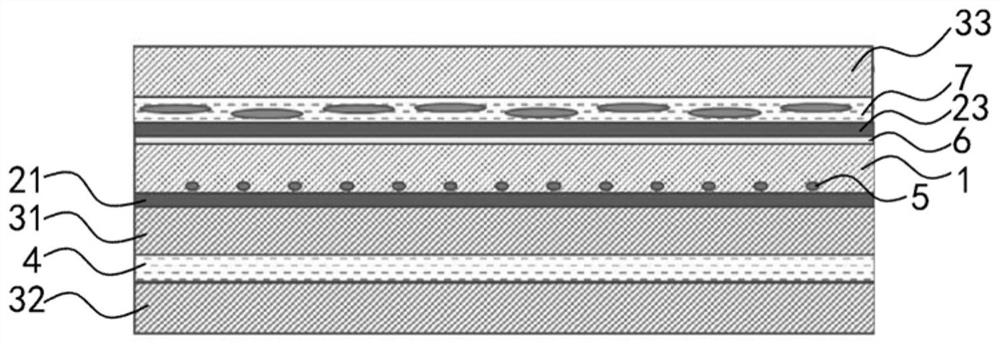
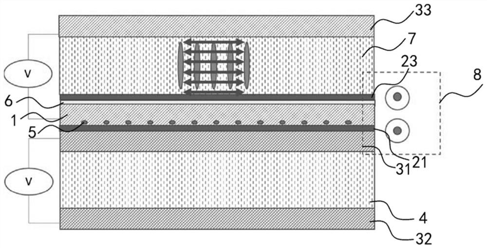
A reflective liquid crystal display panel is provided, comprising: a first substrate and a second substrate oppositely arranged, a first polarizer arranged outside the first substrate, a second polarizer arranged outside the second substrate, and filling the first The liquid crystal between the substrate and the second substrate, the light guide plate with light guide dots arranged on the first polarizer, and the side-type backlight, also include a third layer laminated on the side of the light guide plate opposite to the first polarizer A polarizer, a composite layer with a liquid crystal and a dichroic dye mixture, and a third substrate; the polarization direction of the third polarizer is the same as that of the first polarizer; the light absorption axis of the third polarizer is the same as that of the composite layer when displaying a black state The absorption axis is orthogonal. In the present invention, a polarizer and a dichroic dye compound layer are added above the light guide plate, and the light absorption axis of the polarizer above the light guide plate is perpendicular to the light absorption axis of the dichroic dye compound layer in the display black state, eliminating the light on the surface of the light guide plate. escape, greatly improving the contrast of reflective LCD panels.

Description

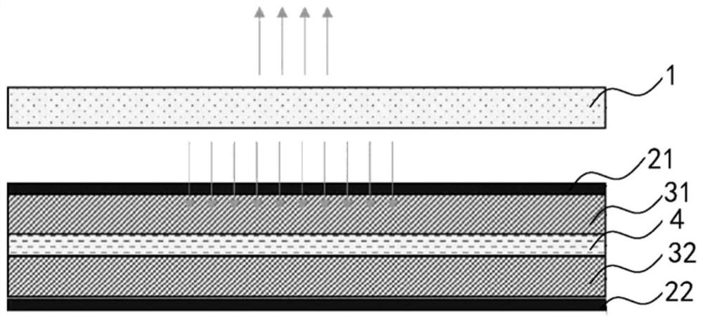
technical field [0001] The invention relates to the field of display technology, in particular to a reflective liquid crystal display panel, a preparation method thereof and a display device. Background technique [0002] Reflective display devices rely on reflecting ambient light to provide a display light source, and the brightness is too low in places with weak ambient light, which limits the scope of use of this type of product. Increasing the front light source can improve the user performance of RLCD in the dark state, improve the grade of the product, increase the added value of the product, and significantly improve the side effect of the product. Taking e-books as an example, the price of a product with a front light source is generally twice that of a product without a front light source. At present, there are few reflective LCD products with front light in major exhibitions at home and abroad, and the main bottleneck is the low contrast. [0003] figure 1 Shown...

Claims


Application Information

Patent Timeline
Patent Type & Authority Patents(China)
IPC IPC(8): G02F1/13357G02F1/1335
CPCG02F1/133524G02F1/133528G02F1/133615G02F1/133618G02B6/0043G02B6/0056G02F1/133553G02F1/13475G02F1/133531G02F1/133616G02F1/133606
Inventor 胡伟频邵喜斌王丹孙晓
Owner BOE TECH GRP CO LTD
Learn More