Liquid crystal display panel

A liquid crystal display panel and display area technology, applied in nonlinear optics, instruments, optics, etc., can solve problems such as yield decline, inability to completely block light leakage, and edge red lines

Active Publication Date: 2018-11-23
WUHAN CHINA STAR OPTOELECTRONICS TECH CO LTD
View PDF6 Cites 3 Cited by
  • Summary
  • Abstract
  • Description
  • Claims
  • Application Information

AI Technical Summary

Problems solved by technology

Limited by the border width of the liquid crystal display panel, the width of the metal wiring on the TFT substrate can only be designed to be very narrow. The risk of light leakage cannot be completely blocked, so there may be risks such as red lines on the edges of the LCD panel and a drop in yield rate

Method used


Image

  • Liquid crystal display panel
  • Liquid crystal display panel
  • Liquid crystal display panel

Examples


Embodiment Construction

[0083] In order to make the object, technical solution and advantages of the present invention clearer, the present invention will be further described in detail below in conjunction with the accompanying drawings. The directional terms mentioned in the present invention, such as [top], [bottom], [front], [back], [left], [right], [inside], [outside], [side], etc., are only for reference The orientation of the attached schema. Therefore, the directional terms used are used to illustrate and understand the present invention, but not to limit the present invention.

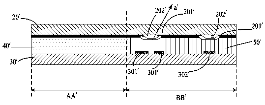
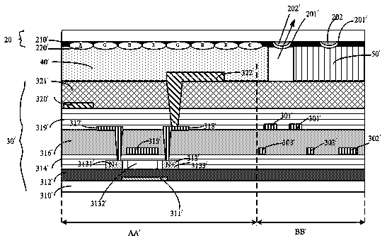
[0084] like Figure 4 Shown is a liquid crystal display panel provided in Embodiment 1 of the present invention, including an array substrate 30, a color filter substrate 20, a liquid crystal layer 40, and a sealant 50; wherein,

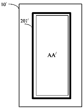
[0085] After the array substrate 30 is assembled with the color filter substrate 20, the display area AA formed on the array substrate 30 corresponds to the display area of ​​the color filt...


PUM


Abstract

The invention provides a liquid crystal display panel. The panel comprises an array substrate, a color film substrate, a liquid crystal layer and bezel glue, after the two substrates are assembled, adisplay area and a non-display area are correspondingly formed, the liquid crystal is located between the two substrates, and a closed area enclosed by the bezel glue is filled with the liquid crystallayer; at least two first metal lines are formed on the non-display area of the array substrate and used for shielding leakage light of a BM groove formed in the side, close to the liquid crystal layer, of the non-display area of the color film substrate; the array substrate further comprises a shading plate, the shading plate is arranged in the non-display area of the array substrate and locatedbelow the two first metal lines, and the length of the shading plate is greater than or equal to the spacing between the two first metal lines to eliminate the phenomenon of edge red lines occurringon the BM groove. By utilizing the liquid crystal display panel, the shading plate is additionally arranged in the non-display area of the array substrate and located below the metal lines used for shielding the leakage light of the BM groove of the color film substrate to eliminate the phenomenon of edge red lines, and the product yield is improved.

Description

technical field [0001] The invention relates to the technical field of liquid crystal display, in particular to a liquid crystal display panel. Background technique [0002] The structure of the liquid crystal display panel is mainly composed of a thin film transistor array (Thin Film TransistorArray, TFT Array) substrate, a color filter (Color Filter, CF) substrate, and a liquid crystal layer (Liquid Crystal Layer) arranged between the two substrates. Its working principle is to control the rotation of the liquid crystal molecules in the liquid crystal layer by applying a driving voltage on the two substrates, and refract the light from the backlight module to generate a picture. [0003] like figure 1 As shown, the LCD panel 10 / In order to prevent electrostatic (ESD) damage during the process, it will be displayed on the display area AA / around (i.e. non-display area BB / ) design multiple BM (black matrix) slots 201 / , the BM slotting 201 / Set on the non-displa...

Claims


Application Information

Patent Timeline
Patent Type & Authority Applications(China)
IPC IPC(8): G02F1/1362G02F1/1368
CPCG02F1/136204G02F1/136209G02F1/136227G02F1/136286G02F1/1368G02F2202/22
Inventor 谷超
Owner WUHAN CHINA STAR OPTOELECTRONICS TECH CO LTD
Why Eureka
Try Eureka