A liquid crystal display panel

A liquid crystal display panel and display area technology, applied in instruments, nonlinear optics, optics, etc., can solve the problems of edge red lines, unable to completely block light leakage, yield decline, etc., to improve product yield and enhance ESD resistance. , the effect of eliminating the edge red line phenomenon

Active Publication Date: 2021-07-13
WUHAN CHINA STAR OPTOELECTRONICS TECH CO LTD
View PDF6 Cites 0 Cited by
  • Summary
  • Abstract
  • Description
  • Claims
  • Application Information

AI Technical Summary

Problems solved by technology

Limited by the border width of the liquid crystal display panel, the width of the metal wiring on the TFT substrate can only be designed to be very narrow. The risk of light leakage cannot be completely blocked, so there may be risks such as red lines on the edges of the LCD panel and a drop in yield rate

Method used


Image

  • A liquid crystal display panel
  • A liquid crystal display panel
  • A liquid crystal display panel

Examples


Embodiment Construction

[0083] In order to make the objects, technical solutions, and advantages of the present invention, the present invention will be further described in detail below with reference to the accompanying drawings. The direction term mentioned in the present invention, for example [upper], [next], [front], [after], [left], [right], [within], [outer], [side], etc., is only reference Additional pattern direction. Therefore, the direction term used is used to illustrate and understand the invention, not to limit the invention.

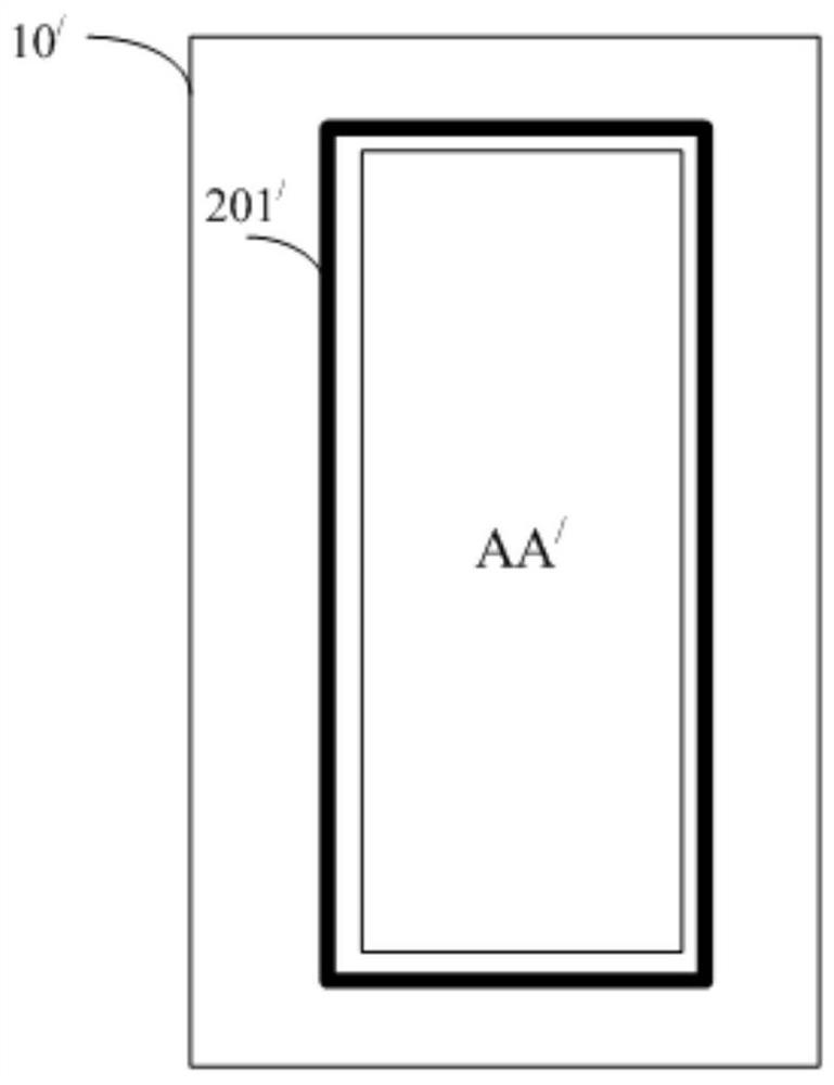
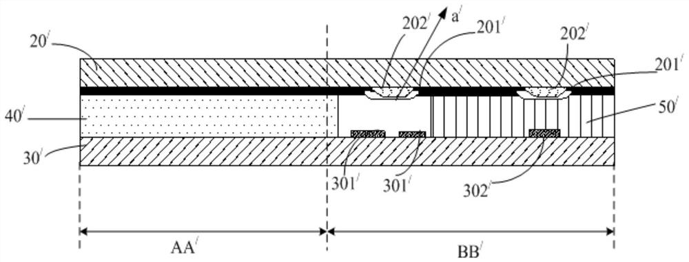
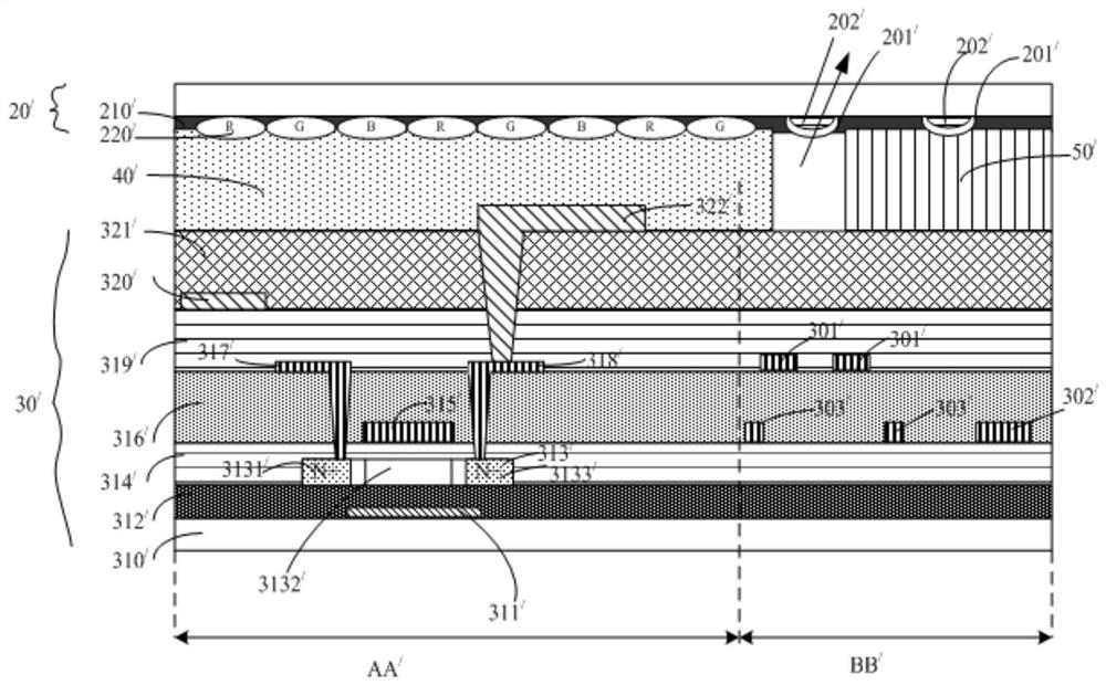
[0084] Such as Figure 4 As shown in the first embodiment of the present invention, a liquid crystal display panel provided, including an array substrate 30, a color film substrate 20, a liquid crystal layer 40, and a frame glue 50;

[0085] After the array substrate 30 is assembled from the color film substrate 20, the display area Aa formed on the array substrate 30 corresponds to the display area of ​​the color film substrate 20, and the non-display area BB formed ...


PUM


Abstract

The invention provides a liquid crystal display panel, comprising an array substrate, a color filter substrate, a liquid crystal layer and a sealant. After the two substrates are assembled, a corresponding display area and a non-display area are formed, and the liquid crystal layer is located between the two substrates and filled with the sealant. In the enclosed area surrounded by; at least two first metal traces are formed on the non-display area of ​​the array substrate to block light leakage from the BM trench provided on the side of the non-display area of ​​the color filter substrate close to the liquid crystal layer; wherein, The array substrate further includes a light-shielding plate, which is disposed in the non-display area of ​​the array substrate and below the two first metal traces and whose length is greater than or equal to the distance between the two first metal traces To eliminate the edge red line phenomenon in the BM groove. In the implementation of the present invention, a shielding plate is added in the non-display area of ​​the array substrate under the metal traces that shield light leakage from the BM groove of the color filter substrate, so as to eliminate the edge red line phenomenon in the BM groove and improve the product yield.

Description

Technical field [0001] The present invention relates to the field of liquid crystal display, and more particularly to a liquid crystal display panel. Background technique [0002] The structure of the liquid crystal display panel is mainly composed of a thin film transistorrray, a TFT Array substrate, a color film (Color filter, CF) substrate, and a liquid crystal layer disposed between two substrates, and is constituted by Liquid Crystal Layer. The working principle is to control the rotation of the liquid crystal molecules of the liquid crystal layer on the two substrates, reflect the light of the backlight module to generate a picture. [0003] Such as figure 1 As shown, the liquid crystal display panel 10 / In the process of anti-static (ESD), it will be in the display area AA / 4 weeks (ie non-display area BB / ) Design multiple BM (black matrices) tap 201 / , This BM tap 201 / The non-display area provided in the CF substrate. [0004] Such as figure 2 As shown, in order to...

Claims


Application Information

Patent Timeline
Patent Type & Authority Patents(China)
IPC IPC(8): G02F1/1362G02F1/1368
CPCG02F1/136204G02F1/136209G02F1/136227G02F1/136286G02F1/1368G02F2202/22
Inventor 谷超
Owner WUHAN CHINA STAR OPTOELECTRONICS TECH CO LTD
Why Eureka
Try Eureka