Stepping motor driving device and stepping motor driving method

A technology of stepping motors and driving devices, which is applied in the direction of motor generator control, electrical components, control systems, etc., can solve problems such as difficulty in adjustment, time-consuming, and limitations in the improvement of indexing feed performance, and achieve suppression of heat generation and vibration high speed effect

Inactive Publication Date: 2018-11-23
TOKYO WELD CO LTD
View PDF9 Cites 0 Cited by
  • Summary
  • Abstract
  • Description
  • Claims
  • Application Information

AI Technical Summary

Problems solved by technology

In the former method, the acceleration and deceleration of the stepping motor is adjusted by the timing of the input pulse, but it is difficult to adjust the timing
In addition, there is a limit to the performance improvement of such index feed by timing adjustment.
On the other hand, in the latter stage, it takes time to generate the current waveform supplied to the stepping motor
In addition, when using the former method for 2-phase excitation, the maximum torque cannot be output during microstepping.

Method used


Image

  • Stepping motor driving device and stepping motor driving method
  • Stepping motor driving device and stepping motor driving method
  • Stepping motor driving device and stepping motor driving method

Examples


no. 1 Embodiment approach

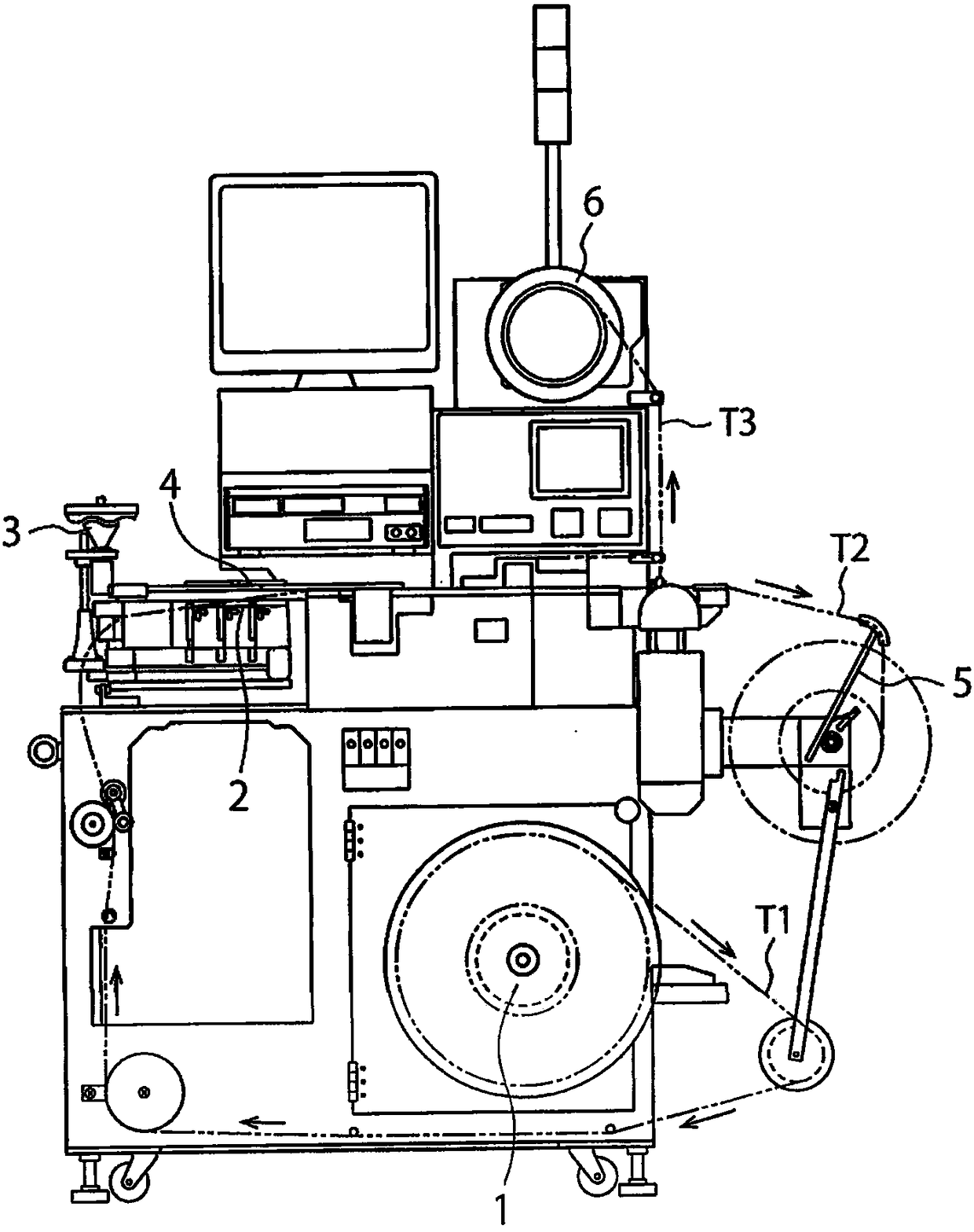
[0035] figure 1 It is a front view showing the structure of the tape tie machine of 1st Embodiment.

[0036] figure 1 The tape machine adopts indexing method, including tape supply reel holding part 1, indexing table 2, parts feeder 3, soldering iron part 4, finished tape holding part 5 and top tape reel holding part 6. figure 1 The tape machine is used for tape of chip electronic components such as capacitors.

[0037] The tape machine conveys the tape T1 from the tape supply reel holding unit 1 via the index table 2 , and conveys the parts from the parts feeder 3 . Components from the component feeder 3 are welded to the tape T1 from the index table 2 by the soldering iron unit 4 . Then, the finished tape T2 obtained from the tape T1 is sent to the finished tape holding section 5 , and the top tape T3 remaining on the tape T1 is sent to the top tape reel holding section 6 .

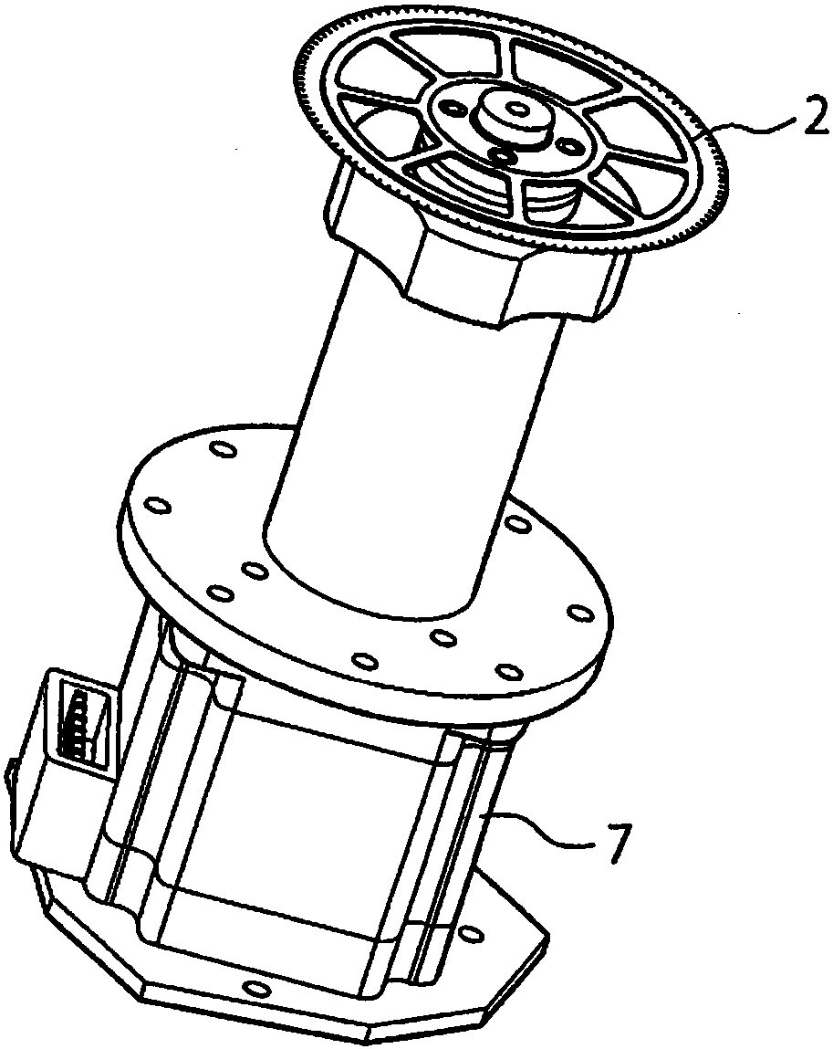
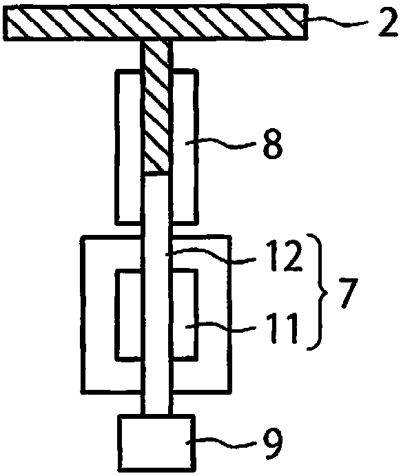
[0038] figure 2 It is a perspective view which shows the structure of the index table 2 etc. w...

no. 2 Embodiment approach

[0096] Figure 12 It is a graph showing temporal changes of the first current IA and the second current IB in the second embodiment. In this embodiment, differences from the first embodiment will be mainly described, and a detailed description of the points common to the first embodiment will be omitted.

[0097] In the first embodiment, the first and second coils 13A and 13B are driven by two-phase excitation, but in this embodiment, the first and second coils 13A and 13B are driven by one-phase excitation.

[0098] exist Figure 12 Among them, the first current IA changes to the first value I1, the third value I3, and zero, and the second current IB changes to the second value I2, the fourth value I4, and zero. Here, the first value I1 and the fourth value I4 are positive values, and the second value I2 and third value I3 are negative values. However, the absolute value of the second value I2 and the absolute value of the fourth value I4 are set smaller than the absolute ...


PUM


Abstract

The present invention provides a stepping motor driving device and a stepping motor driving method capable of suppressing heat generation and vibration of a stepping motor while achieving high speed driving thereof. The stepping motor driving device (10) includes: a pulse generating portion (21) that generates a pulse signal for driving control of the stepping motor (7); and a current control portion (22) used for varying first current (IA) supplied to a first coil (13A) of the stepping motor (7) and varying second current (IB) supplied to a second coil (13B) of the stepping motor (7) when thestepping motor (7) drives basic stepping angles.

Description

technical field [0001] The invention relates to a stepping motor driving device and a stepping motor driving method for driving a stepping motor. Background technique [0002] A stepping motor is a motor suitable for accurate positioning, and is used, for example, in an index table-type tape-tying machine, a component inspection machine, and the like. In this case, as a method for improving the productivity of the banding machine and the parts inspection machine, it is conceivable to increase the operating speed of the index table. The indexing table is equipped with the pocket (pocket, pit) for conveying parts in accordance with the operating angle (basic step angle) of the stepping motor. Therefore, in order to improve the productivity of the belting machine and the parts inspection machine, high Acceleration and deceleration increase the operating frequency of the stepping motor per unit time. [0003] Therefore, conventionally, the operating frequency of the stepping m...

Claims


Application Information

Patent Timeline
Patent Type & Authority Applications(China)
IPC IPC(8): H02P8/10H02P8/12
CPCH02P8/10H02P8/12H02P8/22H02P8/32
Inventor 安藤雄太
Owner TOKYO WELD CO LTD
Why Eureka
Try Eureka