Shaft, bearing and motor

a technology of bearings and motors, applied in the direction of machines/engines, nanoinformatics, liquid fuel engines, etc., can solve the problems of increasing friction between the two, increasing reducing the vibration and noise of the motor, so as to reduce vibration and noise, and reduce vibration and noise during operation

Inactive Publication Date: 2005-03-10
SHINANO KENSHI
View PDF7 Cites 26 Cited by
  • Summary
  • Abstract
  • Description
  • Claims
  • Application Information

AI Technical Summary

Benefits of technology

[0009] A first object of the present invention is to provide a shaft capable of reducing vibration and noise.
[0010] A second object of the present invention is to provide a bearing capable of reducing vibration and noise.
[0011] A third object of the present invention is to provide a motor capable of reducing vibration and noise during operation.
[0028] In the present invention, the carbon nano fibers or carbon nano tubes are included in the sliding section of the shaft and / or the bearing, so that friction, vibration and noise can be reduced. Namely, the motor capable of reducing vibration and noise can be realized. Since the carbon nano fibers and the carbon nano tubes have high heat conductivity, heat generated in the sliding section can be restricted so that fusion of the shaft and the bearing can be prevented. Enough lubricating property can be gained without using lubricant. If lubricant is used, the lubricating property can be further improved, so that an oil film can be maintained without spreading oil. Therefore, the friction, the vibration and the noise can be further reduced.

Problems solved by technology

However, the conventional ball bearings and slide bearings cannot satisfy the requests of high speed motors.
Therefore, friction between the both increased, and vibration and noise of the motors are also increased.
In the case of using a lubricating oil, heat caused by the frictional resistance deteriorates the oil, an oil film is broken and the oil is spread.
In the case of using no lubricating oil, heat generation, vibration and noise must be further increased, so that the fusion is apt to occur.
Therefore, the liquid bearing has the problems as well as the conventional slide bearing.

Method used


Image

  • Shaft, bearing and motor
  • Shaft, bearing and motor

Examples


Embodiment Construction

[0032] Preferred embodiments of the present invention will now be described in detail with reference to the accompanying drawings.

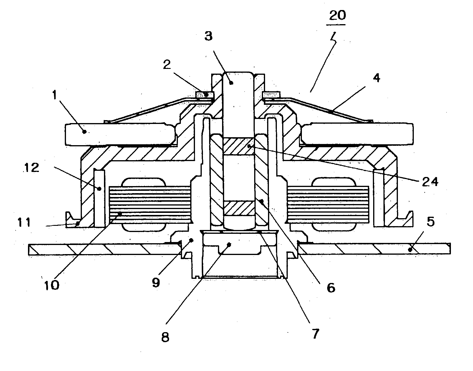
[0033] A polygon scanner motor of an embodiment of the present invention is shown in FIG. 1.

[0034] The polygon scanner motor 20 has a rotor cup 11, which is fixed to a rotor shaft 3 and rotated together with the rotor shaft 3. A ring magnet 12 is fixed on an inner face of the rotor cup 11.

[0035] The rotor shaft 3 is rotatably held by a cylindrical bearing 6 and a thrust bearing 7, which are provided in a housing 9 vertically extended from a circuit board 5. The thrust bearing 7 is provided on an upper face of an end cover 8. The end cover 8 is screwed with the housing 9.

[0036] A stator core 10 is fixed on an outer circumferential face of the housing 9. Lines are wound on the stator core 10 so as to form coils.

[0037] A polygon mirror 1 is fixed to the rotor cup 11. The polygon mirror 1 is pressed and held by a mirror spring 4. A movement of the mirror...


PUM

PropertyMeasurementUnit
Diametersaaaaaaaaaa
Diametersaaaaaaaaaa
speedaaaaaaaaaa

Abstract

The shaft and the bearing are capable of reducing vibration and noise of a motor. The shaft comprises: a shaft proper; and a sliding section provided to the shaft proper, the sliding section including carbon nano fibers or carbon nano tubes. On the other hand, the bearing comprises: a bearing proper; and a sliding section provided to the bearing proper, the sliding section including carbon nano fibers or carbon nano tubes.

Description

BACKGROUND OF THE INVENTION [0001] The present invention relates to a shaft, a bearing and a motor having the shaft and / or the bearing. [0002] The motor of the present invention is mainly used for, for example, a spindle motor for a magnetic disk drive unit, a spindle motor for an optical disk drive unit, a fan motor, a polygon scanner motor, which should be capable of precisely operating, rotating at high speed, having a long span of life and reducing vibration and noise. [0003] Conventionally, the motors for said use have bearings, e.g., slide bearings, liquid bearings, ball bearings. [0004] These days, the motors are often driven at high speed, e.g., 10,000 rpm or more. For example, the spindle motor for driving magnetic disks or optical disks is operated at rotational speed of 20,000 rpm; the polygon scanner motor is operated at rotational speed of 40,000 rpm. And, extending their span of lives and precise operation are required. Further, reducing vibration and noise are also re...

Claims


Application Information

Patent Timeline
Patent Type & Authority Applications(United States)
IPC IPC(8): F16C33/18F04D29/04F04D29/056F04D29/057F16C33/04F16C33/12F16C33/14F16C33/20F16C33/24H02K5/16H02K5/167H02K5/24H02K7/08H02K21/22
CPCB82Y10/00F04D29/0566F04D29/057F16C33/043F16C33/121H02K5/1675H02K5/24H02K7/085F16C33/201F16C2240/40F16C2240/70
Inventor KAKEGAWA, KAZUHIKOENDO, MORINOBU
Owner SHINANO KENSHI
Why Eureka
Try Eureka