Antenna configuration method, device, equipment and storage medium of terminal

An antenna configuration and antenna technology, which is applied in the field of communication, can solve the problems of heavy design workload, high hardware requirements of terminal equipment, poor implementation effect, etc., achieve optimal performance, scientific and feasible comparison method, and improve the ability of the antenna to receive signals Effect

Active Publication Date: 2018-11-23
TP-LINK
View PDF8 Cites 3 Cited by
  • Summary
  • Abstract
  • Description
  • Claims
  • Application Information

AI Technical Summary

Problems solved by technology

[0005] In view of this, the embodiments of the present invention provide a terminal antenna configuration method, device, device, and storage medium to solve the existing technologies that have high hardware requirements for terminal equipment, heavy design workload, and poor implementation effects. question

Method used


Image

  • Antenna configuration method, device, equipment and storage medium of terminal
  • Antenna configuration method, device, equipment and storage medium of terminal
  • Antenna configuration method, device, equipment and storage medium of terminal

Examples


Embodiment 1

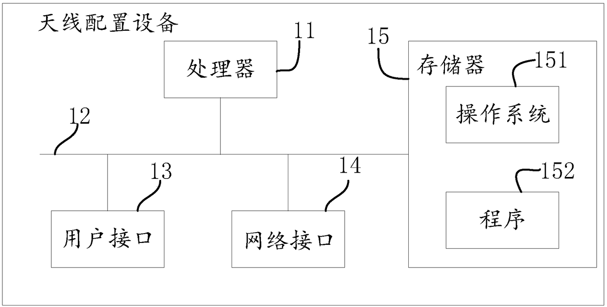
[0057] See figure 1 , figure 1 It is a schematic diagram of the terminal antenna configuration device provided in Embodiment 1 of the present invention; to execute the antenna configuration method of the terminal provided in the embodiment of the present invention, such as figure 1 As shown, the antenna configuration device includes: at least one processor 11, such as CPU, at least one network interface 14 or other user interface 13, memory 15, at least one communication bus 12, and the communication bus 12 is used to realize the connection between these components communication. Wherein, the user interface 13 may optionally include a USB interface, other standard interfaces, and a wired interface. The network interface 14 may optionally include a Wi-Fi interface and other wireless interfaces. The memory 15 may include a high-speed RAM memory, and may also include a non-volatile memory (non-volatile memory), such as at least one disk memory. The memory 15 may optionally in...

Embodiment 2

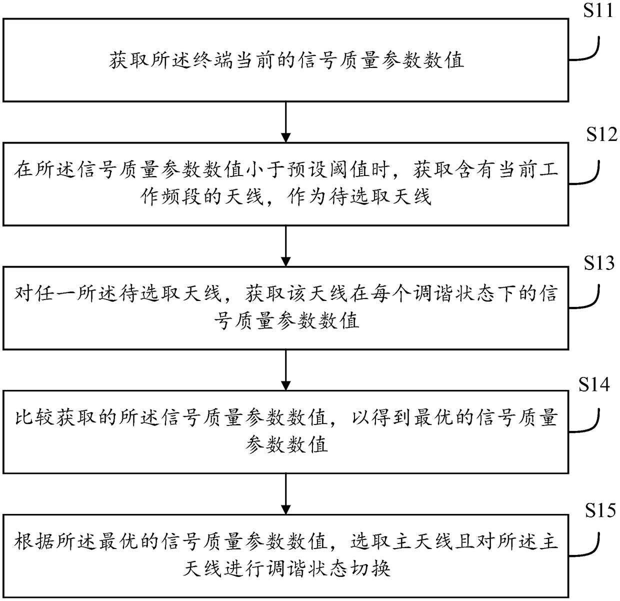
[0067] see figure 2 , figure 2 It is a schematic flowchart of a method for antenna configuration of a terminal provided in Embodiment 2 of the present invention, the terminal includes at least two antennas, and the method includes:

[0068] S11. Obtain the current signal quality parameter value of the terminal.

[0069] In the embodiment of the present invention, the terminal may be a mobile phone, a notebook computer, a wearable device, etc., which is not specifically limited in the present invention.

[0070] In the embodiment of the present invention, the antenna refers to a device that can effectively radiate electromagnetic waves in a specific direction in space or can effectively receive electromagnetic waves in a specific direction in space. Guided waves, transformed into electromagnetic waves propagating in an unbounded medium (usually free space), or vice versa. It can be seen that all antennas have the function of sending and receiving, and there may be some ant...

Embodiment 3

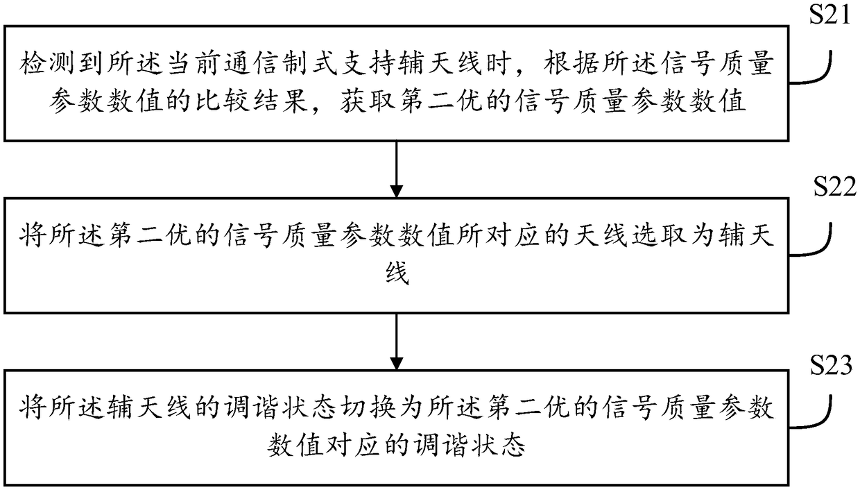
[0111] see image 3 , on the basis of embodiment two, also includes:

[0112] S21. When it is detected that the current communication system supports the auxiliary antenna, according to the comparison result of the signal quality parameter value, obtain the second best signal quality parameter value;

[0113] S22. Select the antenna corresponding to the second best signal quality parameter value as the auxiliary antenna;

[0114] S23. Switch the tuning state of the auxiliary antenna to the tuning state corresponding to the second best signal quality parameter value.

[0115] In the embodiment of the present invention, some communication standards do not support the auxiliary antenna function, for example, 2G, and some communication standards support the auxiliary antenna function, for example, 3G or 4G, when the terminal is connected to the base station, from The current communication standard and whether the current communication standard supports the auxiliary antenna functi...


PUM


Abstract

The invention discloses an antenna configuration method of a terminal. The method comprises the following steps: acquiring the current signal quality parameter value of the terminal; acquiring the antenna containing the current antenna band as the to-be-selected antenna when the signal quality parameter value is less than the preset threshold; and then acquiring the signal quality parameter valueof the antenna under each tuning state for any to-be-selected antenna; comparing the acquired signal quality parameter values to obtain the optimal signal quality parameter value; and finally, selecting the main antenna according to the optimal signal quality parameter value, and performing tuning state switching on the main antenna. The technical problems that the hardware requirement on the terminal equipment is high, the design workload is large and the realization effect is bad are solved, so that current antenna performance of the terminal is optimal, and the antenna signal receiving capacity in the terminal equipment is improved.

Description

technical field [0001] The present invention relates to the field of communication technology, in particular to a terminal antenna configuration method, device, equipment and storage medium. Background technique [0002] Communication technology is to transmit information from the sending end (source) to one or more receiving ends (sink) through electrical pulses in the form of electromagnetic waves, sound waves or light waves. Whether the receiving end can correctly identify the information depends on the power loss during transmission. [0003] With the rapid development of communication technology, there are more and more applications using antenna signal communication. However, the antenna radiation unit is easily affected by the surrounding environment. The usage scenarios of mobile terminals such as mobile phones are complex and diverse. The user's hand-holding method and the surrounding environment of the mobile phone will affect the efficiency of the antenna and aff...

Claims


Application Information

Patent Timeline
IPC IPC(8): H04B7/08H04B7/06
CPCH04B7/0608H04B7/0802H04B7/0825
Inventor 郭富祥
Owner TP-LINK
Why Eureka
Try Eureka