Beam receiving device for tail end of proton beam line

A technology for receiving devices and proton beams, applied in accelerators, electrical components, magnetic resonance accelerators, etc., can solve problems such as difficult and precise positioning, achieve the effects of improving success rate, avoiding random errors, and ensuring safety

Active Publication Date: 2018-11-23
CHINA INSTITUTE OF ATOMIC ENERGY
7 Cites 0 Cited by

AI-Extracted Technical Summary

Problems solved by technology

[0004] Aiming at the problem that existing beam collecting devices are difficult to locate accurately in irradiation experiments, the purpose of the present invention is to provide a bea...

Method used

Considering the problem of heat dissipation and dosage residue, among the present invention, beam current guide plate 1 and beam current blocking piece 2 all adopt aluminum alloy material (preferred model 6061) to make, and reason is that the thermal conductivity of aluminum alloy is relatively high. Strong, with a short residual dose. Preferably, ...

Abstract

The invention discloses a beam receiving device for the tail end of a proton beam line. The beam receiving device comprises a beam lead-in plate (1) for connecting coaxially with the tail end of the proton beam line in an insulated mode, a beam blocking block (2) coaxially connected with the beam lead-in plate (1) in an insulated mode and a cable; a through hole (11) for beam to enter is formed inthe axial center of the end face of the end, depart form the beam blocking block (2), of the beam lead-in plate (1); a mounting groove (21) communicating with the through hole (11) is formed in the side face, facing the beam lead-in plate (1), of the beam blocking block (2), and a beam receiving plate (3) which is perpendicular to the through hole (10) in the axial direction is fixed in the mounting groove (21); and the cable is connected with the beam receiving plate (3). According to the beam receiving device beam, the beam lead-in plate is directly coaxially connected to the tail end of the proton beam line in an insulated mode, the position of the beam receiving device is limited, the influence of human factors is reduced, the randomness error is effectively avoided, and the accuracyof beam collecting and the success rate of experiments are greatly improved.

Application Domain

Magnetic resonance accelerators

Technology Topic

Atomic physicsProton

Image

  • Beam receiving device for tail end of proton beam line
  • Beam receiving device for tail end of proton beam line
  • Beam receiving device for tail end of proton beam line

Examples

  • Experimental program(1)

Example Embodiment

[0027] The present invention will be further described in detail below in conjunction with the drawings.
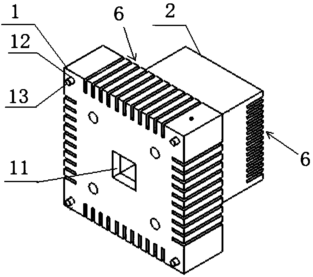
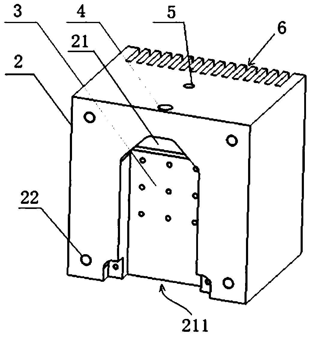
[0028] In fact, the beam receiving device for the end of the proton beam line provided by the present invention is an irradiation experiment device, which is usually set at the end of the proton beam line and used to receive part of the proton beam for irradiation experiments. , And at the same time block the excess proton beam. In order to facilitate the installation of the beam receiving device of the present invention, a counterbore should be opened at the end of the proton beam line in advance.
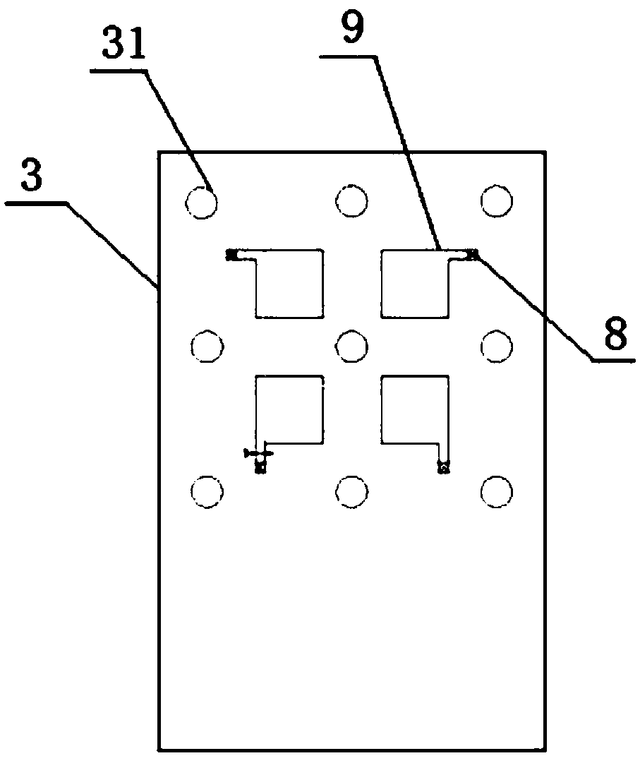
[0029] Such as figure 1 As shown, a beam receiving device for the end of a proton beam line provided by the present invention includes a beam introduction plate 1 and a beam introduction plate that are coaxially insulated and connected to the counterbore at the end of the proton beam line. The board 1 is coaxially insulated and connected with a beam blocking block 2 and a cable (not shown) for transmitting an electronic detection signal. The axial center of the beam introduction plate 1 is provided with a through hole 11 corresponding to the transmission direction of the proton beam line for the beam to enter; the beam blocking block 2 faces the beam introduction plate 1 A mounting groove 21 communicating with the through hole 11 is opened on the side surface, and a beam receiving plate 3 perpendicular to the axial direction of the through hole 10 is fixed in the mounting groove 21. A number of fixing holes 31 are provided on the beam receiving plate 3 so as to be fixed in the mounting groove 21 by inserting screws.
[0030] Considering the problems of heat dissipation and residual dose, in the present invention, both the beam introduction plate 1 and the beam blocking block 2 are made of aluminum alloy material (preferably model 6061), because the thermal conductivity of aluminum alloy is relatively strong, and at the same time The dose remaining time is short. Preferably, the beam introduction plate 1 and the beam blocking block 2 adopt a square structure to facilitate processing.
[0031] In order to better realize natural heat dissipation, the edges of the beam introduction plate 1 and the beam blocking block 2 of the present invention are both provided with a heat dissipation grid structure 6 to increase the heat dissipation area.
[0032] In order to ensure the coaxial connection between the beam introduction plate 1 and the counterbore at the end of the proton beam line, such as figure 1 As shown, a number of mounting holes 12 are provided on the edge of the end face of the beam introduction plate 1 facing away from the beam blocking block 2 symmetrically around the central axis of the through hole 11, and the installation positions of the mounting holes 12 on the beam introduction plate 1 are located Within the corresponding area defined by the size of the counterbore at the end of the proton beam streamline. In this way, when the beam introduction plate 1 is installed, the through holes 11 of the beam introduction plate 1 can be made to correspond to the counterbores, so that the beam at the end of the proton beam line can be accurately introduced into the beam introduction plate 1.
[0033] In order to ensure the insulation between the beam introduction plate 1 and the end of the proton beam line, an insulating spacer is set on the beam introduction plate 1 and the end of the proton beam line, and a customized insulating screw 13 (can be a nylon screw) is used to insert it Into the mounting hole 12 to realize the connection between the beam introduction plate 1 and the end of the proton beam line.
[0034] Also in order to ensure insulation, an insulating gasket is provided between the beam current introducing plate 1 and the beam current blocking block 2; and the edge of the beam blocking block 2 is provided with a number of threaded connection holes 22, which are used for insertion Customized nylon screws to connect the beam introduction plate 1 and the beam blocking block 2.
[0035] Such as image 3 As shown, the component under test 9 used in the irradiation experiment can be installed on the beam receiving plate 3; at the same time, a cable welding position 8 can be opened on the beam receiving plate 3 near the component under test 9, which will be used for transmission The electric signal cable is welded to the cable welding position 8, so that the electronic detection signal about the beam current information (such as dose monitoring information) received by the measured component 9 can be transmitted to the peripheral information control system (not shown) through the cable , Through the information control system to record beam current information and control the opening and closing of the cyclotron.
[0036] Since the heating power of the beam receiving plate 3 is 200W when receiving the beam, excessively high temperature will affect the irradiation experiment. In order to enhance heat dissipation, the beam receiving device of the present invention further includes an air-cooled component arranged on the beam blocking block 2.
[0037] In a preferred embodiment, the air-cooled assembly includes a cold air source 10 connected to the beam blocking block 2. The cold air source 10 may be an air compressor, and the outer surface of the beam blocking block 2 corresponds to the beam flow. The installation position of the receiving plate 3 is provided with a cold air source interface hole 4 communicating with the installation groove 21; the installation groove 21 has an opening 211 on the outer surface of the beam blocking block 2 for exhaust.
[0038] In a more preferred embodiment, the air-cooled assembly may further include a heat dissipation fan 7 arranged at an end of the beam blocking block 2 facing away from the beam introducing plate 1. Preferably, the size of the cooling fan 7 should be larger than the size of the beam blocking block 2, that is, the cooling fan 7 can cover the end of the beam blocking block 2, so as to dissipate the entire beam blocking block 2, which can further improve the heat dissipation efficiency. .
[0039] In addition, in order to monitor the temperature change on the beam receiving plate 3, a temperature measuring hole 5 is also opened on the side of the beam blocking block 2 where the cold air source interface hole 4 is opened, which is used to connect a thermocouple. Set display panel. In this way, the operator can monitor the temperature change in real time, if the temperature is too hot, the experiment will be stopped immediately.
[0040] The structural dimensions of the beam receiving device used in the irradiation experiment for the end of the proton beam line of the present invention are given below:
[0041] Since the penetration distance of 100Mev protons in aluminum is 36mm, in order to block the excess beam, the axial length of the beam introduction plate 1 is selected as 50mm, and the overall size of the beam introduction plate 1 is selected as 155x155x50mm. The size of the measured component 9 (such as a diamond module) on the receiving plate 3 is 20x20mm, and the size of the through hole 11 in the center of the beam introduction plate 1 is 20x20mm; the size of the counterbore at the end of the cyclotron proton beam line is 136x136mm , The installation positions of all the mounting holes 12 on the beam introduction plate 1 should be located in the area limited by the counterbore size of 136x136mm; the thickness of the beam receiving plate 3 is 5mm, considering the installation problem, the self-beam blocking block 2 On the side connected with the beam introduction plate 1, a 14mm deep, 70x44mm installation groove 21 (see figure 2 ), the parallel beam blocking block 2 has four threaded connection holes 22, the horizontal and longitudinal distance between the four threaded connection holes 22 is 80mm, and the four threaded connection holes 22 are evenly distributed in the beam blocking block around the axis 2 On the side facing the beam introduction plate 1, it is used to connect with the beam introduction plate 1; choose to open the M8 cold air source interface hole 4 on the beam blocking block 2 corresponding to the beam receiving plate 3, and An M6 temperature measuring hole 5 is opened on the beam blocking block 2.
[0042] The working process of the beam receiving device used at the end of the proton beam line in the present invention is as follows:
[0043] First install the beam receiving plate 3 in the installation groove 21 of the beam blocking block 2, and then use the threaded connection holes 22 and nylon screws to connect the beam blocking block 2 to the beam introduction plate 1. After the installation is completed, Use the mounting holes 12 and insulating screws 13 to install the obtained beam receiving device at the end of the beam line, start the cyclotron, output the proton beam, and start the air compressor and air-cooled components at the same time; the beam flows through the beam introduction plate 1 The through hole 11 illuminates the component under test 9 on the beam receiving board 3. At the same time, the beam receiving board 3 transmits signals to the peripheral information control system (such as the upper controller) through the cable set in the cable welding position 8. , The information control system records and processes the experimental data, monitors the temperature change in real time through the thermocouple set in the temperature measuring hole 5, and monitors the change trend of the received signal in real time until the experiment is completed.
[0044] This specific embodiment is only an explanation of the present invention, and it is not a limitation of the present invention. After reading this specification, those skilled in the art can make modifications to this embodiment without creative contribution as needed, but as long as the rights of the present invention All requirements are protected by patent law.

PUM

no PUM

Description & Claims & Application Information

We can also present the details of the Description, Claims and Application information to help users get a comprehensive understanding of the technical details of the patent, such as background art, summary of invention, brief description of drawings, description of embodiments, and other original content. On the other hand, users can also determine the specific scope of protection of the technology through the list of claims; as well as understand the changes in the life cycle of the technology with the presentation of the patent timeline. Login to view more.

Similar technology patents

Parking braking control device and method

InactiveCN103496360Aprevent movementensure safety
Owner:GREAT WALL MOTOR CO LTD

Mobile phone shielding device for driver

InactiveCN101364814Aensure safetyFacilitate normal communication
Owner:动力新跃(北京)汽车科技有限公司

Method for managing and logging-on password of remote server based on network

ActiveCN101282252AAvoid password lossensure safety
Owner:SHENGQU INFORMATION TECH SHANGHAI

Classification and recommendation of technical efficacy words

  • Reduce the influence of human factors
  • ensure safety

Coke automatic sample collecting and making method

InactiveCN1580730AReduce the influence of human factorsSimple process
Owner:TIANJIN TIANTIE METALLURGICAL GRP

Method and device for grading and coloring thematic map

InactiveCN101739888AReduce the influence of human factorsSimplify user operations
Owner:BEIJING NORMAL UNIVERSITY

Surrounding rock engineering geology fine classification method in hydropower project

InactiveCN107958333Aimprove accuracyReduce the influence of human factors
Owner:POWERCHINA CHENGDU ENG

Automatic welding equipment

ActiveCN111055015AReduce the influence of human factorsGuarantee welding quality
Owner:GUANGDONG ZHENGYE TECH

High accuracy non-contact tri-dimensional facial type measuring device

InactiveCN101105389Aensure safetylow cost
Owner:中国人民解放军第二炮兵装备研究院第四研究所

Intelligent charger with output voltage changing function

Owner:SHENZHEN SIECOM COMM TECH DEV CO LTD
Why Eureka
Try Eureka