Radar device, wireless rotating device for a radar and unmanned aerial vehicle

A radar device and unmanned aerial vehicle technology, applied in the field of radar, can solve the problems that the 360° omnidirectional rotation of the antenna assembly cannot be realized, and the rotation angle of the driving mechanism is limited.

Active Publication Date: 2018-11-23
SZ DJI TECH CO LTD
View PDF12 Cites 7 Cited by
  • Summary
  • Abstract
  • Description
  • Claims
  • Application Information

AI Technical Summary

Problems solved by technology

In the prior art, a cable is used to connect the antenna assembly and an external power supply to supply power to the antenna assembly. However, in this power supply mode, due to the limitation of the cable, the rotation angle of the driving mechanism will be limited, for example, the rotation angle is only Can reach 270°, making it impossible to achieve 360° omnidirectional rotation of the antenna assembly

Method used


Image

  • Radar device, wireless rotating device for a radar and unmanned aerial vehicle
  • Radar device, wireless rotating device for a radar and unmanned aerial vehicle
  • Radar device, wireless rotating device for a radar and unmanned aerial vehicle

Examples


Embodiment 1

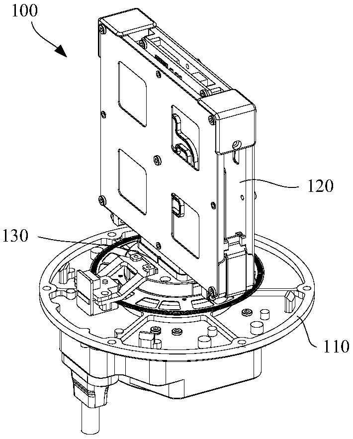
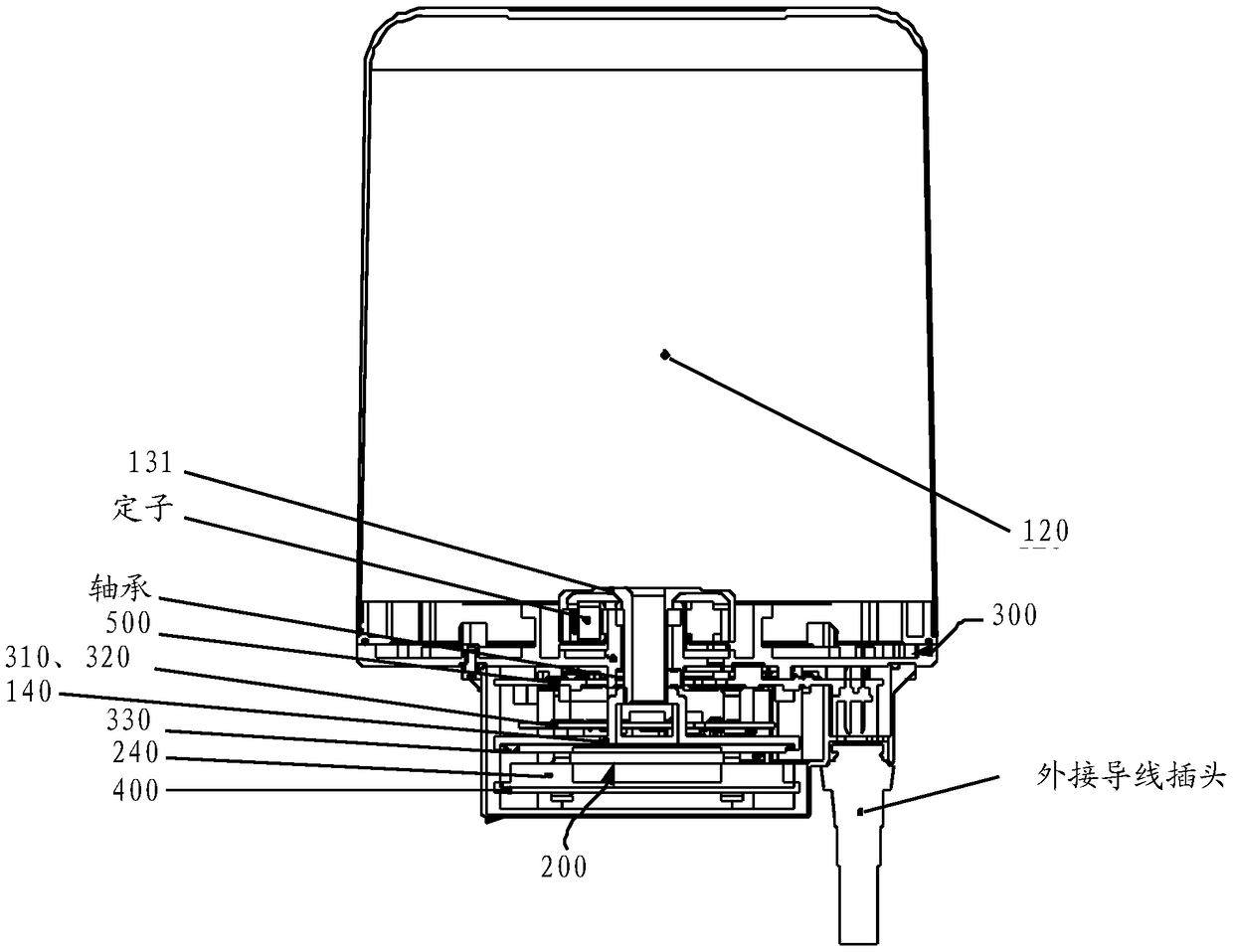
[0017] See figure 1 and figure 2 , are respectively a structural schematic diagram and a cross-sectional view of a radar device 100 provided in the embodiment of the present application, such as figure 1 and figure 2 As shown, the radar device 100 includes a base 110 , an antenna assembly 120 , an antenna bracket 140 for supporting the antenna assembly 120 , a motor 130 , and a power transmitting component 200 and a power receiving component 300 .

[0018] Among them, such as figure 1 As shown, the antenna assembly 120 is arranged on the base 110, and it can rotate around a rotation axis relative to the base 110. It should be noted that the rotation axis can be a real axis or an imaginary axis. When the rotation axis is a real axis, the antenna assembly 120 can rotate relative to the rotating shaft, or the antenna assembly 120 can rotate together with the rotating shaft. The motor 130 is disposed on the base 110 , which may include a rotor 131 connected to the antenna as...

Embodiment 2

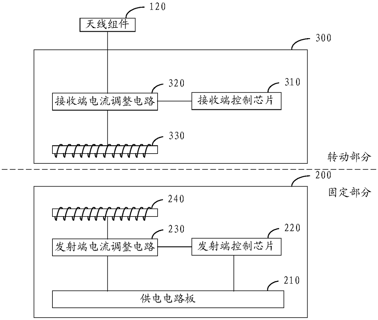
[0050]The radar wireless rotating device provided in the embodiment of the present application may include: a base, an antenna component, a power transmitting component, and a power receiving component. Wherein, the antenna component can be arranged on the base, and can rotate around a rotating shaft relative to the base, the electric energy transmitting component can be used to convert electric energy into electromagnetic energy, and emit the electromagnetic energy, and the electric energy receiving component, and The antenna assembly is electrically connected and rotatable with the antenna assembly, and can be used to convert received electromagnetic energy into electrical energy and transmit the converted electrical energy to the antenna assembly. The specific structure, working principle, working process, and realized working effect of the wireless rotating device of the radar may be similar to the radar device described in the first embodiment above, and will not be repeat...

Embodiment 3

[0054] See Figure 5 , is an unmanned aerial vehicle provided in the embodiment of the present application. The unmanned aerial vehicle may include a housing 610 and a radar device 620, wherein the radar device 620 may be arranged on the housing 610, and its antenna assembly ( Figure 5 not shown) can communicate with the UAV's control system ( Figure 5 Not shown in ), to establish a communication connection between the obstacle information detected by the antenna assembly to be sent to the control system, and the control system can control the flight of the UAV according to the received obstacle information to realize the flight Avoidance.

[0055] For the specific structure, working principle, working process and working effect of the radar device 620, reference may be made to the related description in the above-mentioned first embodiment, and details will not be repeated here.

[0056] As follows, further Figure 5 The example drone is shown for illustration. See Fi...


PUM


Abstract

The present invention provides a radar device, a wireless rotating device for a radar, and an unmanned aerial vehicle, wherein the radar device comprises: a base; an antenna assembly disposed on the base, and the antenna assembly rotating about a rotating shaft with respect to the base; an electrical energy emitting component for converting electrical energy into electromagnetic energy and emitting the electromagnetic energy; and a power receiving component disposed at an interval from the electrical energy transmitting component, wherein the electrical energy receiving component is electrically connected to the antenna component, and is rotated with the antenna assembly for converting received electromagnetic energy into electrical energy and transmitting the converted electrical energy to the antenna assembly. With the radar device, the antenna assembly can be rotated 360 degrees omnidirectionally.

Description

technical field [0001] The present application relates to the technical field of radar, in particular to a radar device, a wireless rotating device for radar and an unmanned aerial vehicle. Background technique [0002] With the rapid development of UAV technology and the improvement of radar miniaturization technology, radar has gradually become an important part of the UAV load, and the antenna component is the core component of the radar. The driving function can rotate around a rotating shaft to detect obstacles in different directions. In the prior art, a cable is used to connect the antenna assembly and an external power supply to supply power to the antenna assembly. However, in this power supply mode, due to the limitation of the cable, the rotation angle of the driving mechanism will be limited, for example, the rotation angle is only It can reach 270°, so it is impossible to realize 360° omnidirectional rotation of the antenna assembly. Contents of the invention...

Claims


Application Information

Patent Timeline
Patent Type & Authority Applications(China)
IPC IPC(8): G01S7/02
CPCG01S7/02G01S7/006G01S7/027Y02T50/60G01S13/933B64C1/36B64C39/024B64D41/00H04W84/12B64U10/13
Inventor 匡亮亮王春明王佳迪贺翔
Owner SZ DJI TECH CO LTD
Why Eureka
Try Eureka