
aircraft

A technology of aircraft and microcontroller, applied in the field of aircraft, to achieve the effects of simple maintenance, guaranteed integrity, and flexible use possibilities

Active Publication Date: 2022-05-27
LIEBHERR AEROSPACE LINDENBERG
View PDF5 Cites 0 Cited by
  • Summary
  • Abstract
  • Description
  • Claims
  • Application Information

AI Technical Summary

Problems solved by technology

[0003] A disadvantage here is that the electrical interface is only compatible with certain types of sensors or analog interfaces or can only be used to actuate certain drive elements or other components
[0004] Therefore, using the same electronic device for different applications is only very limited or impossible according to the prior art

Method used


Image

  • aircraft
  • aircraft

Examples


Embodiment Construction

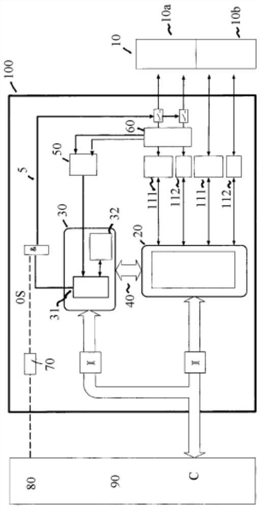
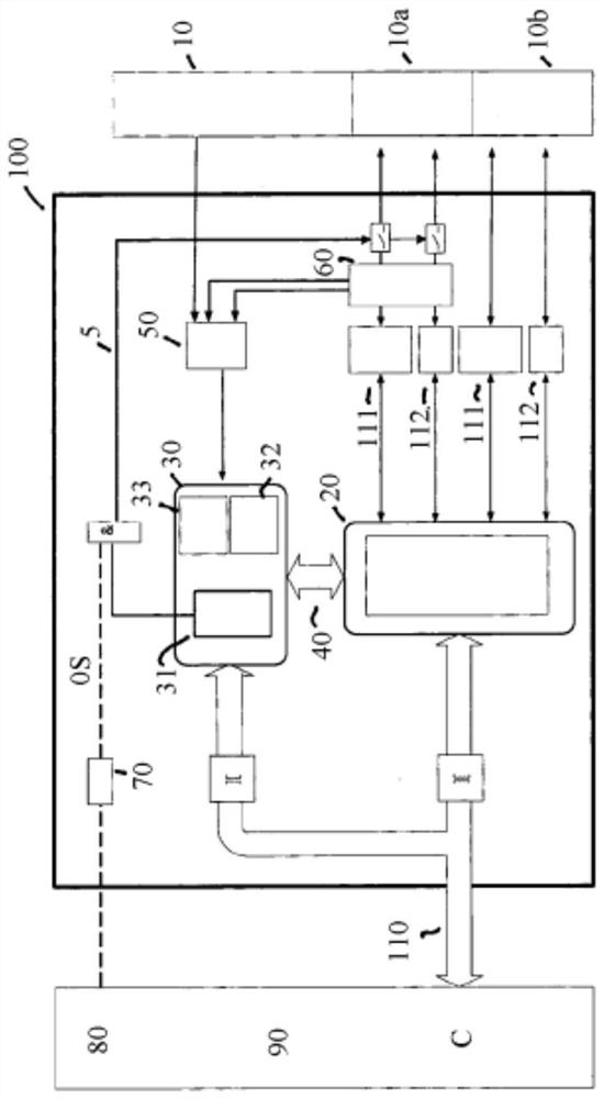
[0035] exist figure 1 The middle electronic device is denoted by reference numeral 100 . Reference numeral 10 designates critical and non-critical interfaces or sensors, wherein critical and non-critical interfaces or sensors are provided in area 10a and non-critical interfaces or sensors are provided or provide their signals in area 10b.

[0036] As can be further seen from the figures, the non-critical signals according to 10b are transmitted to the discrete input / output module (In / Out) of the power switch 111 or to the analog input / output module (Input / Output) 112 . A corresponding situation applies to critical and non-critical interfaces or sensors 10a, which are likewise transmitted to units 111 and 112, wherein a configurable signal correlation device 60 is provided between these two components. Accordingly, the electronic device preferably has, in addition to the microcontroller 30 and one or more FPGA cores 20, a mechanism for a configurable signal correlation device...


PUM


Abstract

The invention relates to an aircraft having at least one component and having at least one electronic device for actuating the component, wherein the electronic device has at least one interface by means of which a signal for actuating the component is provided, wherein the electronic device has a A combination of at least one microcontroller and at least one FPGA core, the at least one microcontroller and at least one FPGA core being connected to each other via a communication link, wherein the FPGA core can be configured such that different signals can be processed depending on the configuration of the FPGA core.

Description

technical field [0001] The invention relates to an aircraft with at least one component and with at least one electronic device for actuating the component, wherein the electronic device has at least one interface by means of which signals for actuating the component are provided. Background technique [0002] The use of so-called remote electronic units (REUs) is known from the prior art, which are adapted for specific applications in order to be used only for the associated electrical interface. [0003] The disadvantage here is that the electrical interface is only compatible with certain types of sensors or analog interfaces or can only be used for actuating certain drive elements or other components. [0004] Therefore, according to the prior art, using the same electronic device for different applications is only very limited or impossible. SUMMARY OF THE INVENTION [0005] The invention is therefore based on the object of improving an aircraft of the type mentioned...

Claims


Application Information

Patent Timeline
Patent Type & Authority Patents(China)
IPC IPC(8): G05D1/00B64C13/50G05B19/05G05B23/02G06F15/78
CPCG05B19/0421B64D43/00G06F13/4027G05D1/0077H04L12/40032H04L2012/4028
Inventor 赖内·米尔扎雷克弗兰克·克伦布格
Owner LIEBHERR AEROSPACE LINDENBERG
Learn More