Spacer fabric, spacer fabric section and heatable cladding element

A technology of knitted fabrics and segments, which is applied in the direction of knitting, warp knitting, electric heating fuel, etc., and can solve the problems that cannot be realized, consume preparation quality, and produce peculiar smell, etc.

Inactive Publication Date: 2017-03-15
MULLER TEXTIL
View PDF8 Cites 4 Cited by
  • Summary
  • Abstract
  • Description
  • Claims
  • Application Information

AI Technical Summary

Problems solved by technology

Especially with the textile materials mentioned, since the open textile structures are often still difficult to bond, due to the additional adhesives, odors can arise during use or additional costs can be incurred during disposal or recycling.
[0007] DE20220752U1 discloses a textile material laminated by at least two layers. In this two-dimensional material, one layer consists of conductive yarns and one layer consists of non-conductive yarns. The textile material without any cushioning effect Production is also expensive.
[0008] From DE102006038611A1 and DE102006038612A1 known spacer knits of the same type comprising conductive yarns arranged in a first knitted fabric layer, which generally describe different variants of such spacer knits for heating purposes. One of the knitted The layer can consist entirely of conductive yarns, especially metal wires, metal stranded wires are recommended as solid wires are difficult to handle on knitting machines and most common metal wires can be placed in spacer knits, but cannot be combined with each other
[0009] Although there is a great demand for easy-to-use spacer knits that can be heated, the spacer knits described in DE 10 2006 038 611 A1 and DE 10 2008 038 612 A1 cannot be realized in practice
This is especially attributable to the inability to prepare corresponding materials of satisfactory quality at reasonable expense.

Method used


Image

  • Spacer fabric, spacer fabric section and heatable cladding element
  • Spacer fabric, spacer fabric section and heatable cladding element
  • Spacer fabric, spacer fabric section and heatable cladding element

Examples


Embodiment Construction

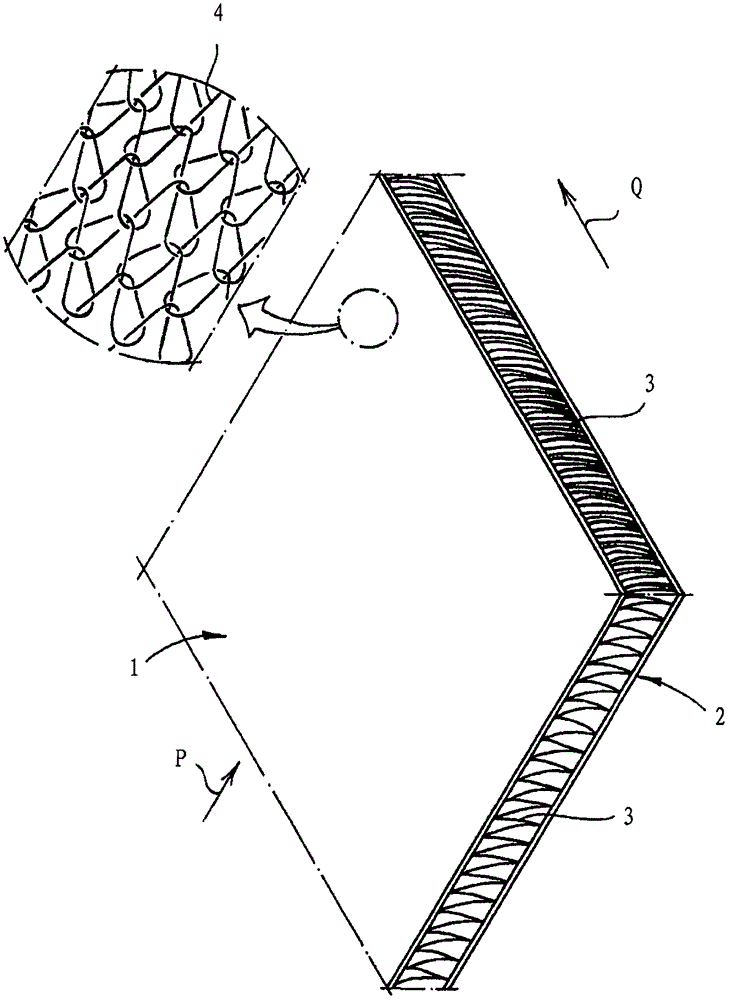
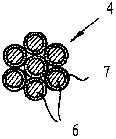
[0060] figure 1 The basic structure of a spacer knitted fabric according to the invention is shown with a first areal knitted fabric layer 1 , a second areal knitted fabric layer 2 and a spacer yarn 3 connecting the knitted fabric layers 1 , 2 . The first knitted fabric layer 1 has conductive yarns 4 which are bonded underneath image 3 Further explanation.

[0061] according to figure 1 As shown, the entire first knitted fabric layer 1 is composed of conductive yarns 4, according to figure 1 As shown in the detailed diagram of , the conductive yarn 4 is arranged in the warp knitting lap yarn (Trikot-Legung), so that the conductive yarn 4 in the first knitted fabric layer 1 forms loops on two stitches. By forming the loops so that Adjacent conductive yarns 4 are tightly interwoven with each other and are electrically connected to each other on the surface of conductive yarns 4 through direct electrical contact.

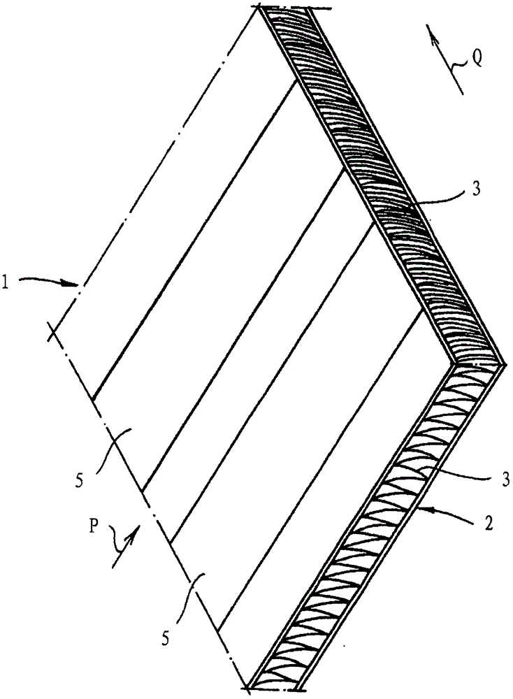
[0062] figure 1 and figure 2 The spacer knits shown diff...


PUM


Abstract

The invention relates to a spacer fabric, a spacer fabric section and a heatable cladding element. The spacer fabric includes a face-shaped first fabric layer (1) having a transmission yarn (4), a face-shape fabric layer (2) and a spacer yarn (3) which is connected to the fabric layers (1, 2). The conduction yarn (4) has a conductive coating (7). A conduction stripe (5) which extends comprehensively in the first fabric layer (1) or along a production direction has adjacent conduction yarns which are in direct electrical connection. The conduction yarn (4) forms a coil with an inlay in at least two coil columns in the first fabric layer (1), and in a conductive synthesized material yarn (4), the content of the conductive coating (7) is less than 50 weight %. The invention also relates to a spacer fabric section composed of the spacer fabric and a heatable cladding element which has the spacer fabric section and a covering layer.

Description

technical field [0001] The invention relates to a spacer knitted fabric comprising a planar first knitted fabric layer with conductive yarns, a planar second knitted fabric layer and spacer yarns connecting the knitted fabric layers, the conductive yarns having The electrically conductive coating and adjacent conductive threads are connected to one another in direct electrical contact over the entire surface of the first knitted fabric layer or in the conductive strips extending in the production direction. Background technique [0002] Various methods are known for equipping spacer knitted fabrics with electrical conductors, especially for heating purposes. [0003] According to DE19903070A1, DE102009013250B3 and DE4239068A1, individual heating wires which are not connected to one another and which extend in the production direction can be brought into contact with connecting conductors which extend transversely. The contact connection is relatively complex, and the range ...

Claims


Application Information

Patent Timeline
Patent Type & Authority Applications(China)
IPC IPC(8): D04B21/00F24C7/06
CPCD04B21/16D10B2403/021D04B21/00F24C7/06
Inventor S·米勒F·米勒
Owner MULLER TEXTIL
Why Eureka
Try Eureka