Handle and vacuum cleaner shell structure and vacuum cleaner

A technology for vacuum cleaners and handles, which is applied in the direction of vacuum cleaners, handles, cleaning equipment, etc. It can solve the problems of handle deformation, overall strength imbalance, damage, etc., and achieve the goal of increasing structural strength, overall strength and local strength balance, and improving overall strength. Effect

Active Publication Date: 2018-11-27
NINGBO HAIJI ELECTRIC APPLIANCE
View PDF7 Cites 2 Cited by
  • Summary
  • Abstract
  • Description
  • Claims
  • Application Information

AI Technical Summary

Problems solved by technology

However, due to the different matching and limiting structures on the two halves (one half is provided with a ring of protrusions, and the other half is provided with a ring of grooves), the overall strength is very uneven, which makes the handle easily partially deformed even damaged

Method used


Image

  • Handle and vacuum cleaner shell structure and vacuum cleaner
  • Handle and vacuum cleaner shell structure and vacuum cleaner
  • Handle and vacuum cleaner shell structure and vacuum cleaner

Examples


Embodiment 1

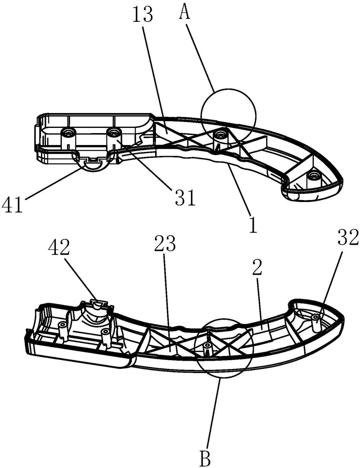
[0030] Embodiment 1: as figure 1 , figure 2 , image 3 as shown in

[0031] a handle, including

[0032] The left half body 1 and the right half body 2 that can be fitted and fixed to each other; the left half body is provided with a left half cavity inside, and the right half body is provided with a right half cavity inside, and the side of the left half body facing the right half body is the left half body. Matching side, the side of the right half facing the left half is the right matching side;

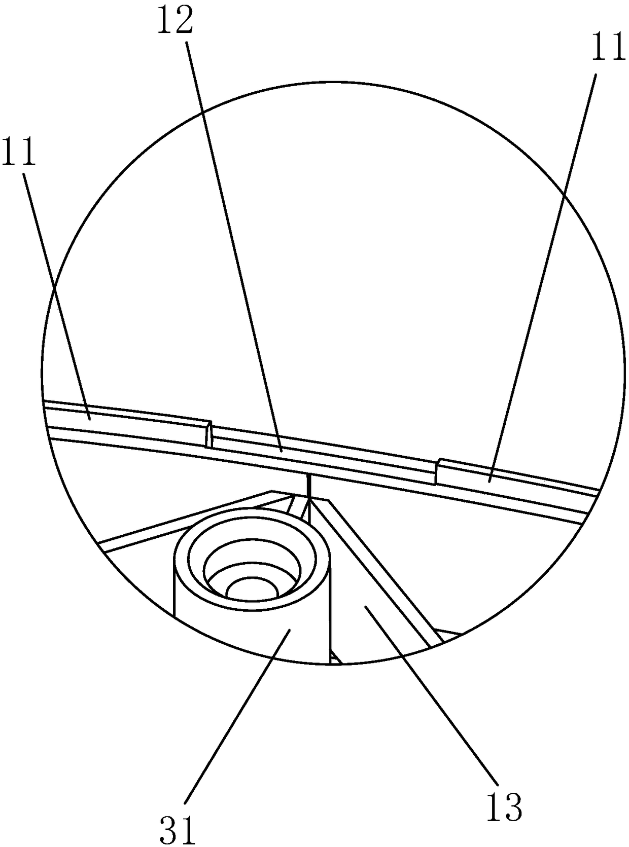
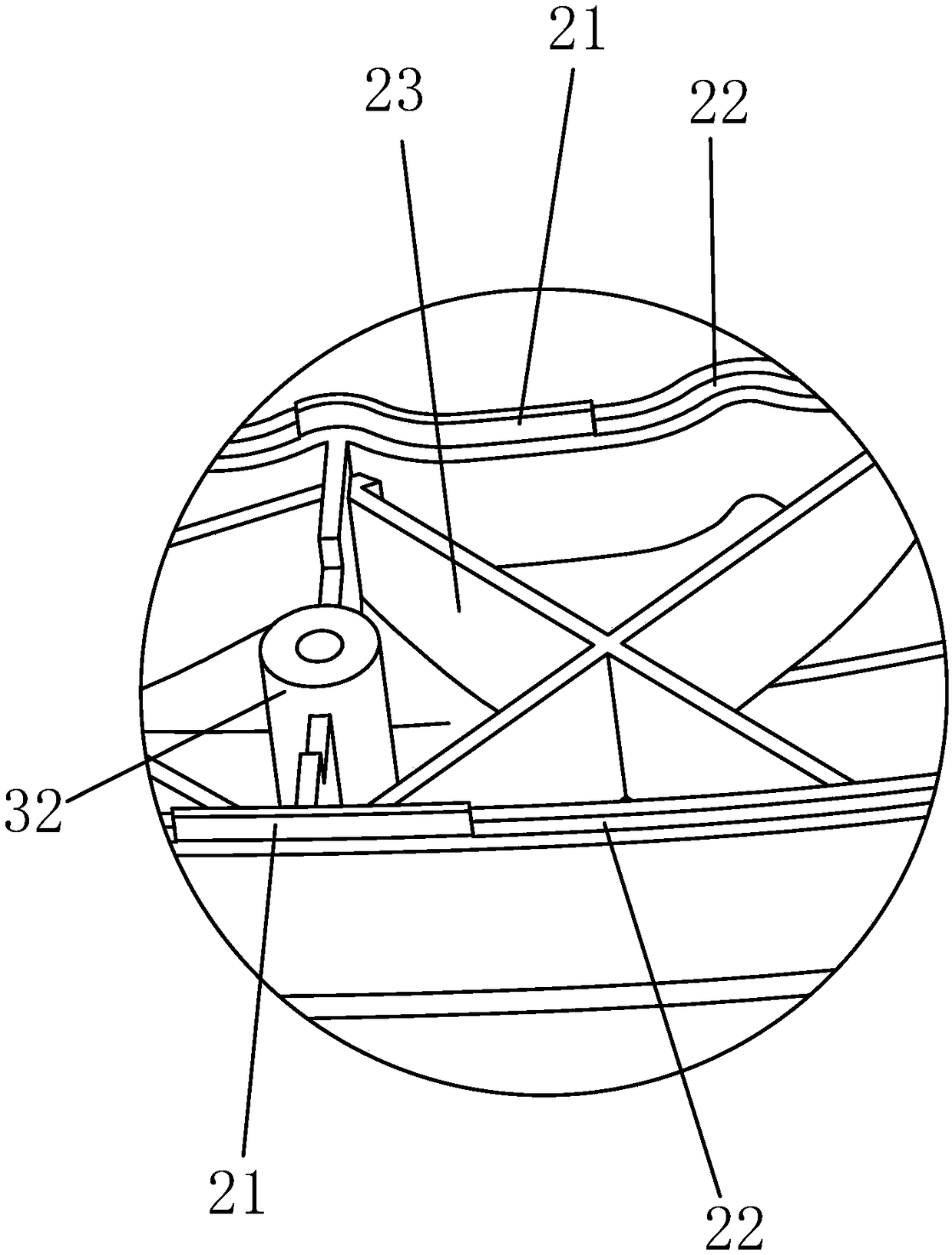
[0033] The left half body is provided with a number of left flanges 11 and a number of left grooves 12, the left flange is arranged on the left matching side, the left groove opens on the left matching side, and the right half is provided with a number of right flanges 21 And several right grooves 22, the right flange is arranged on the right matching side, and the right groove opens on the right matching side;

[0034] The left flange is in one-to-one correspondence with th...

Embodiment 2

[0042] A shell structure of a vacuum cleaner, comprising a left half shell and a right half shell that can fit and fix each other; the side of the left half shell facing the right half shell is the left matching shell surface, and the side of the right half shell facing the left half shell is The right matching shell surface; the left half shell is provided with a number of left shell flanges and a number of left shell grooves, the left shell flange is arranged on the left matching shell surface, the left shell groove opens on the left matching shell surface, and the right half shell The shell is provided with a number of right shell flanges and a number of right shell grooves, the right shell flange is arranged on the right matching shell surface, and the right shell groove opens on the right matching shell surface; the left shell flange and the right shell groove One-to-one correspondence, the right shell flange is in one-to-one correspondence with the left shell groove, the ...

Embodiment 3

[0044] Embodiment 3: based on embodiment 1, as Figure 4 as shown,

[0045] A vacuum cleaner, including a handle as described in Embodiment 1, and also includes a casing 5, a dust cup 51, a handle hard tube 6, a dust mop 7 and a dust collection motor 8, the dust cup is provided with a first The air inlet and the first air outlet, the dust cup is provided with a filter cartridge 511 between the air inlet of the vacuum motor and the first air inlet, the main exhaust port, the first air inlet, and the first air outlet are arranged on the casing , the air inlet of the dust collection motor, the air outlet of the dust collection motor and the main exhaust port are connected in sequence, the mop chamber 7a is provided inside the mop for dust collection, and the bottom suction port 7b connected with the mop chamber is provided on the mop for dust collection and communicated with the mop chamber The upper air outlet pipe 71, the upper air outlet pipe is clamped and communicated with ...


PUM


Abstract

The invention discloses a handle, comprising a left half body and a right half body; The left half body is provided with a left half cavity, the right half body is provided with a right half cavity, one side of the left half body facing the right half body is a left matching side, and one side of the right half body facing the left half body is a right matching side; A plurality of left flanges and a plurality of left grooves are arranged on the left half body, the left flanges are arranged on the left mating side surface, the left grooves are opened on the left mating side surface, the righthalf body is provided with a plurality of right flanges and a plurality of right grooves, the right flanges are arranged on the right mating side surface, and the right grooves are opened on the rightmating side surface. The left flange is stuck in the corresponding right groove and the right flange is stuck in the corresponding left groove. The invention has the advantages that the distributionof the limit structure on the two halves is relatively balanced, the overall strength after assembly is good, and the problems of local easy deformation and easy damage can be avoided.

Description

technical field [0001] The invention belongs to the technical field of vacuum cleaners, in particular to a handle and a vacuum cleaner. Background technique [0002] Among the vacuum cleaners, there is a type of hand-held vacuum cleaner. The characteristic of the hand-held vacuum cleaner is that it can be separated from the vacuum mop. When the vacuum mop is not used, it can directly vacuum and clean high places, walls, etc. When mopping the dust floor, the ground can be vacuumed and cleaned. A hand-held vacuum cleaner generally includes a handle hard tube and a handle arranged at the end of the handle hard tube for assisting in gripping. In the prior art, in order to ensure light weight, the handle is mostly a hollow injection molded part, which is composed of two halves (left half handle, right half handle) butted. One of the half bodies is provided with a circle of protrusions, and the other half body is provided with a circle of grooves, and the protrusions and the gro...

Claims


Application Information

Patent Timeline
Patent Type & Authority Applications(China)
IPC IPC(8): A47L9/32A47L9/00A47L5/28
CPCA47L5/28A47L9/00A47L9/322
Inventor 周荣郑良宝
Owner NINGBO HAIJI ELECTRIC APPLIANCE
Why Eureka
Try Eureka