Centrifugal cleaning machine for optical lens

A technology of centrifugal cleaning and optical lenses, which is applied in the direction of cleaning flexible objects, chemical instruments and methods, cleaning methods and utensils, etc. It can solve the problems of spraying influence, direct action of particles, and scratches, etc., to reduce the possibility of scratches High efficiency, cost reduction, and high spray utilization

Active Publication Date: 2018-11-27
江西省长益光电有限公司
View PDF6 Cites 0 Cited by
  • Summary
  • Abstract
  • Description
  • Claims
  • Application Information

AI Technical Summary

Problems solved by technology

[0002] In the production process of the lens, it is inevitable that static electricity will be generated to absorb the dust in the air, which will affect the cleanliness of the lens itself and affect the subsequent processes such as coating and assembly. In the prior art, ordinary The water flow is washed from top to bottom, but this cleaning method cannot effectively remove the attachments on the surface of the lens, and may cause relatively hard particles to directly act on the lens and cause scratches, and the existing centrifugal rotation will damage the lens. Due to the influence of spraying, it is difficult to ensure a comprehensive cleaning on the surface of the lens, and it is difficult to ensure the cleanliness because manual loading and unloading is required each time

Method used


Image

  • Centrifugal cleaning machine for optical lens
  • Centrifugal cleaning machine for optical lens
  • Centrifugal cleaning machine for optical lens

Examples


Embodiment Construction

[0015] The present invention will be further described below in conjunction with the accompanying drawings and specific embodiments.

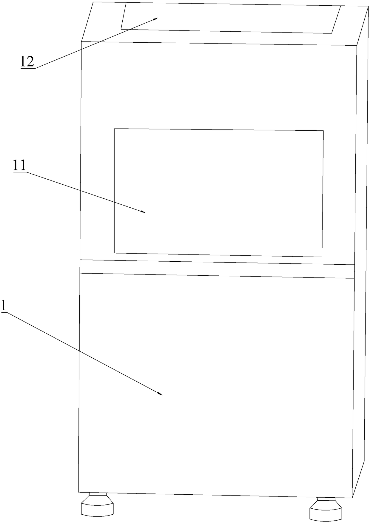
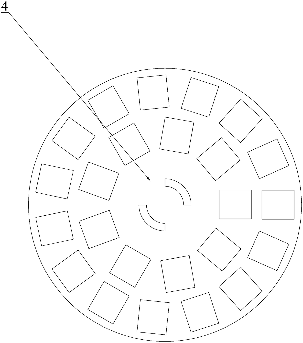
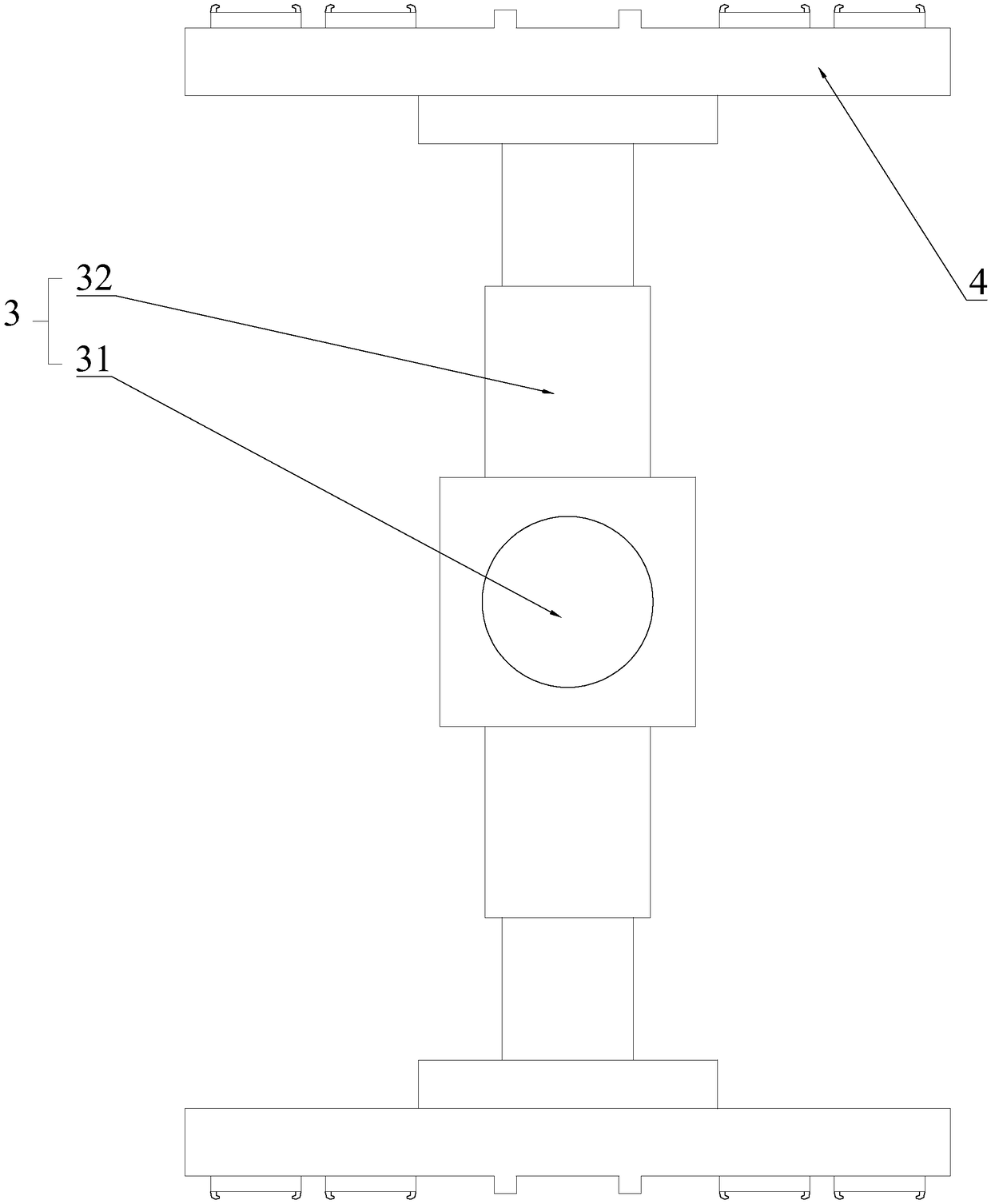
[0016] see figure 1 , figure 2 , image 3 and Figure 4 As shown, the optical lens centrifugal cleaning machine of the present invention includes a housing 1, the housing 1 is provided with an inlet 11 and an outlet 12, and the inlet 11 and the outlet 12 are provided with a conveying track 2, and also includes The loading carousel 4 and the rotating mechanical arm 3 arranged in the housing 1 also include a rotating shaft 5 located at the lower side of the loading carousel 4, and a spray assembly 6 is fixedly connected to the rotating shaft 5, and the spray assembly 6 6 includes a spray body 62 fixedly connected to the rotating shaft 5 and nozzles 61 arranged along the circumference of the spray body 62. The spray body 62 is detachably connected to the loading carousel 4, and the spray body 62 is connected to the loading carousel. Circumfer...


PUM


Abstract

The invention discloses a centrifugal cleaning machine for optical lens, aiming to guarantee low possibility of generating scratch while achieving complete cleaning of surfaces of optical lens and achieving feeding and discharging without manual work. The technical scheme includes that the centrifugal cleaning machine comprises a casing provided with an inlet and an outlet, and further comprises acarrier turn plate, a rotating mechanical arm and a rotation shaft; both the inlet and the outlet are provided with conveying rails, the carrier turn plate and the rotating mechanical arm are arranged in the casing, the rotation shaft is arranged at the lower side of the carrier turn plate, and a spraying assembly is fixedly connected to the rotation shaft; the spraying assembly comprises a mainsprayer fixedly connected to the rotating shaft and nozzles arranged around the main sprayer, the main sprayer is detachably connected with the carrier turn plate and limited circumferentially with the carrier turn plate, and the rotating mechanical arm is used for grabbing the carrier turn plate to the conveying rails or the main sprayer.

Description

technical field [0001] The invention relates to the field of lens cleaning equipment, in particular to a centrifugal cleaning machine for optical lenses. Background technique [0002] In the production process of the lens, it is inevitable that static electricity will be generated to absorb the dust in the air, which will affect the cleanliness of the lens itself and affect the subsequent processes such as coating and assembly. In the prior art, ordinary The water flow is washed from top to bottom, but this cleaning method cannot effectively remove the attachments on the surface of the lens, and may cause relatively hard particles to directly act on the lens and cause scratches, and the existing centrifugal rotation will damage the lens. Due to the impact of spraying, it is difficult to ensure comprehensive cleaning on the surface of the lens, and manual loading and unloading is required each time, making it difficult to ensure cleanliness. Contents of the invention [00...

Claims


Application Information

Patent Timeline
Patent Type & Authority Applications(China)
IPC IPC(8): B08B3/02B08B13/00B08B11/00
CPCB08B3/022B08B11/00B08B13/00
Inventor 王锦平王杰
Owner 江西省长益光电有限公司
Why Eureka
Try Eureka