Optical lens centrifugal cleaning machine

A technology for centrifugal cleaning and optical lenses, which is applied in the direction of cleaning flexible objects, cleaning methods and utensils, chemical instruments and methods, etc. It can solve the problems of ineffective removal of lens surface attachments, difficulty in ensuring lens surface cleaning, and impact on lens cleanliness, etc. question

Active Publication Date: 2021-06-22
江西省长益光电有限公司
View PDF6 Cites 0 Cited by
  • Summary
  • Abstract
  • Description
  • Claims
  • Application Information

AI Technical Summary

Problems solved by technology

[0002] In the production process of the lens, it is inevitable that static electricity will be generated to absorb the dust in the air, which will affect the cleanliness of the lens itself and affect the subsequent processes such as coating and assembly. In the prior art, ordinary The water flow is washed from top to bottom, but this cleaning method cannot effectively remove the attachments on the surface of the lens, and may cause relatively hard particles to directly act on the lens and cause scratches, and the existing centrifugal rotation will damage the lens. Due to the influence of spraying, it is difficult to ensure a comprehensive cleaning on the surface of the lens, and it is difficult to ensure the cleanliness because manual loading and unloading is required each time

Method used


Image

  • Optical lens centrifugal cleaning machine
  • Optical lens centrifugal cleaning machine
  • Optical lens centrifugal cleaning machine

Examples


Embodiment Construction

[0016] The present invention will be further described below in conjunction with the accompanying drawings and specific embodiments.

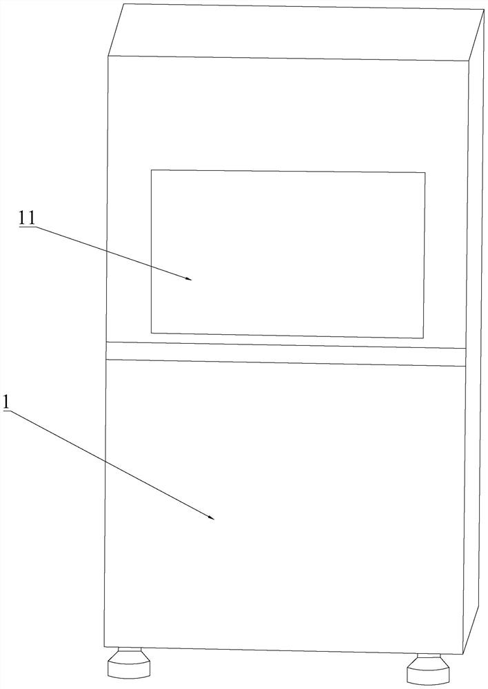
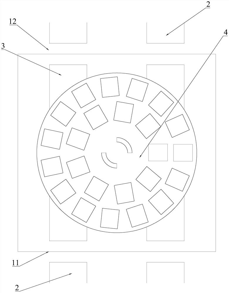
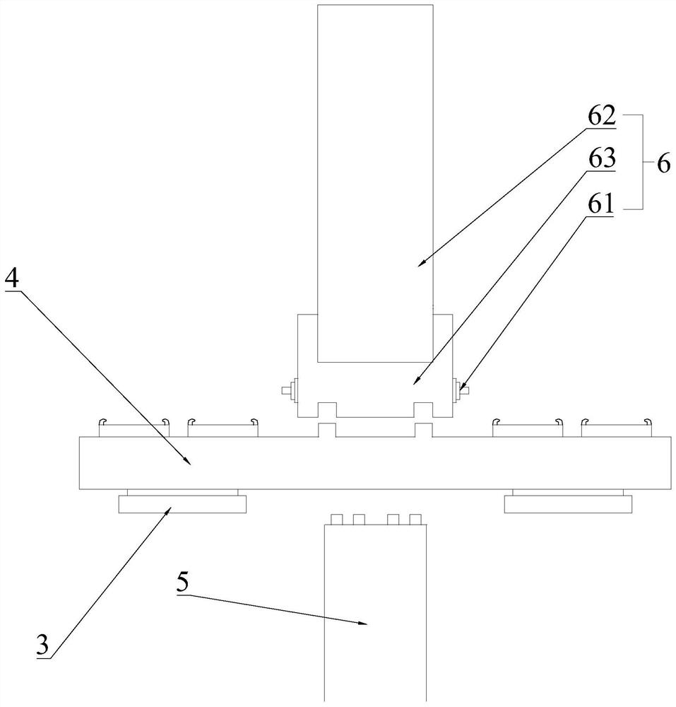
[0017] see figure 1 , figure 2 , image 3 and Figure 4 As shown, the optical lens centrifugal cleaning machine of the present invention includes a housing 1, and the housing 1 is provided with an inlet 11 and an outlet 12, and the inlet 11 and the outlet 12 are provided with two conveying conveyors arranged in parallel. The track 2, the housing 1 is provided with an auxiliary track 3, and also includes a loading carousel 4 arranged in the housing 1, and also includes a rotating shaft 5 located on the lower side of the loading carousel 4, and also includes a The spray assembly 6 on the upper side, the rotating shaft 5 rises and falls in the axial direction, the rotating shaft 5 rises to separate the loading carousel 4 from the auxiliary track 3 and conflicts with the spraying assembly 6, after the rotating shaft 5 rises, the rotating shaft ...


PUM


Abstract

The invention discloses a centrifugal cleaning machine for optical lenses, which can not only ensure comprehensive cleaning on the surface of the lens, but also reduce the possibility of scratches, and does not require manual loading and unloading. The housing is provided with an inlet and an outlet, and the inlet and the outlet are provided with two parallel conveying rails, and the housing is provided with auxiliary rails, and also includes a loading carousel arranged in the housing, and also includes The rotating shaft located on the lower side of the loading turntable also includes a spray assembly located on the upper side of the loading turntable. The rotating shaft rises and falls in the axial direction, and the rising of the rotating shaft makes the loading turntable and the auxiliary track disengage and interfere with the spray assembly, and the rotating shaft rises The rear rotating shaft and the loading turntable are limited in the circumferential direction, and the rotating shaft or the loading turntable drives the spray assembly to rotate. The spray assembly is provided with a number of nozzles, and the nozzles are arranged radially along the loading turntable.

Description

technical field [0001] The invention relates to the field of lens cleaning equipment, in particular to a centrifugal cleaning machine for optical lenses. Background technique [0002] In the production process of the lens, it is inevitable that static electricity will be generated to absorb the dust in the air, which will affect the cleanliness of the lens itself and affect the subsequent processes such as coating and assembly. In the prior art, ordinary The water flow is washed from top to bottom, but this cleaning method cannot effectively remove the attachments on the surface of the lens, and may cause relatively hard particles to directly act on the lens and cause scratches, and the existing centrifugal rotation will damage the lens. Due to the impact of spraying, it is difficult to ensure comprehensive cleaning on the surface of the lens, and manual loading and unloading is required each time, making it difficult to ensure cleanliness. Contents of the invention [00...

Claims


Application Information

Patent Timeline
Patent Type & Authority Patents(China)
IPC IPC(8): B08B3/02B08B13/00B08B11/00
CPCB08B3/022B08B11/00B08B13/00
Inventor 王锦平王杰
Owner 江西省长益光电有限公司
Why Eureka
Try Eureka