Chamfering device

A technology of chamfering device and chamfering mechanism, which is applied in the field of mechanical processing, can solve problems such as errors in processing positions, and achieve the effect of accurate material positioning

Active Publication Date: 2018-11-27
嘉善信道五金塑料模具厂
View PDF8 Cites 0 Cited by
  • Summary
  • Abstract
  • Description
  • Claims
  • Application Information

AI Technical Summary

Problems solved by technology

However, the existing chamfering device does not have a positioning mechanism during use, resulting in an error in the processing position

Method used


Image

  • Chamfering device
  • Chamfering device
  • Chamfering device

Examples


Embodiment Construction

[0023] In order to make the technical means, creative features, goals and effects achieved by the present invention easy to understand, the present invention will be further elaborated below in conjunction with illustrations and specific embodiments.

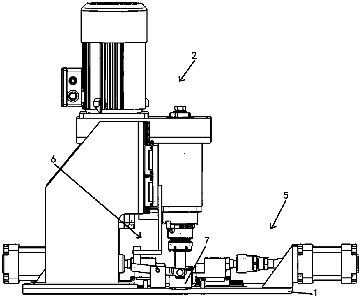
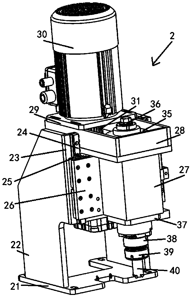
[0024] Such as Figure 1 to Figure 6 As shown, a kind of chamfering device proposed by the present invention includes a base plate 1 and a chamfering mechanism 2 installed on the base plate; a clamping mechanism 5 and a material retaining mechanism 6 are also installed on the base plate 1; the chamfering device Also includes a clamping mechanism 5, the clamping mechanism 5 includes a first clamping group 51 and a second clamping group 52, the first clamping group 51 and the second clamping group 52 are symmetrical and have the same structure; The first clamping group 51 includes a first clamping cylinder 511, and the first clamping cylinder 511 is fixed on the left side of the first cylinder mounting plate 512; the left side of ...


PUM


Abstract

The invention discloses a chamfering device. The chamfering device comprises a bottom plate and a chamfering mechanism arranged on the bottom plate; a clamping mechanism and a stopping mechanism are further installed on the bottom plate; the chamfering device further comprises the clamping mechanism which comprises a first clamping set and a second clamping set, and the first clamping set and thesecond clamping set are in left-and-right symmetry and are identical in structure; the first clamping set comprises a first clamping air cylinder which is fixed to the left side face of a first air cylinder installing plate; a first triangular plate is fixedly arranged between the left side face of the first air cylinder installing plate and the bottom plate; a first sliding block is fixed to an output shaft of the first clamping air cylinder and fixed to a first slider, the first slider is slidingly arranged on a first slide rail, and the first slide rail is fixedly arranged on the bottom plate; a first clamping block is fixed to the right end of the first sliding block.

Description

technical field [0001] The invention relates to the field of machining, in particular to a chamfering device. Background technique [0002] In order to remove the burrs produced by machining on the parts and to facilitate the assembly of the parts, chamfers are generally made on the ends of the parts. In addition, in the process of hardware production and processing, a necessary process is chamfering. However, the existing chamfering device does not have a positioning mechanism to cause errors in the processing position during use. [0003] The present invention is the improvement carried out in order to solve the above problems. Contents of the invention [0004] The object of the present invention is to provide a chamfering device. [0005] The technical scheme that the present invention adopts for solving its technical problem is: [0006] A chamfering device, comprising a bottom plate and a chamfering mechanism installed on the bottom plate; [0007] A clamping me...

Claims


Application Information

Patent Timeline
Patent Type & Authority Applications(China)
IPC IPC(8): B23Q3/08B23D79/00
CPCB23D79/00B23Q3/08
Inventor 张春梦
Owner 嘉善信道五金塑料模具厂
Why Eureka
Try Eureka