Internal support clamp and clamping device

A technology of internal support fixtures and clamping devices, which is applied in the direction of chucks, manufacturing tools, manipulators, etc., and can solve the problems that cavity parts cannot meet the requirements of clamping and moving

Pending Publication Date: 2018-11-27
BEIJING SOFT ROBOT TECH CO LTD
View PDF0 Cites 10 Cited by
  • Summary
  • Abstract
  • Description
  • Claims
  • Application Information

AI Technical Summary

Problems solved by technology

[0002] Currently used fixtures, such as traditional cylinder jaws, rubber, silicone airbags, etc., cannot meet the needs of clamping and moving for cavity parts

Method used


Image

  • Internal support clamp and clamping device
  • Internal support clamp and clamping device
  • Internal support clamp and clamping device

Examples


Embodiment 1

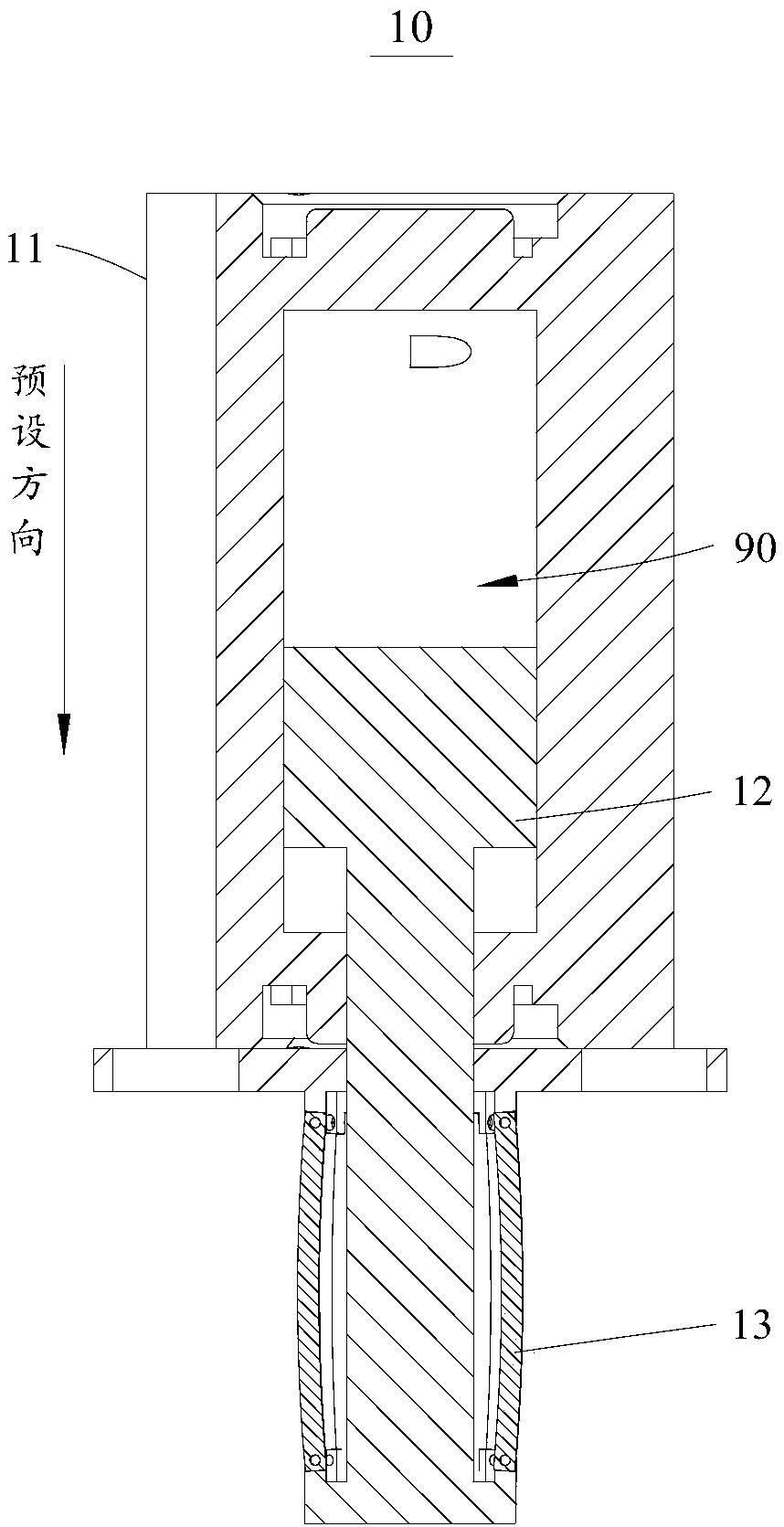
[0047] This embodiment provides an inner support jig 10 , which meets the requirements of clamping and moving cavity-type parts.

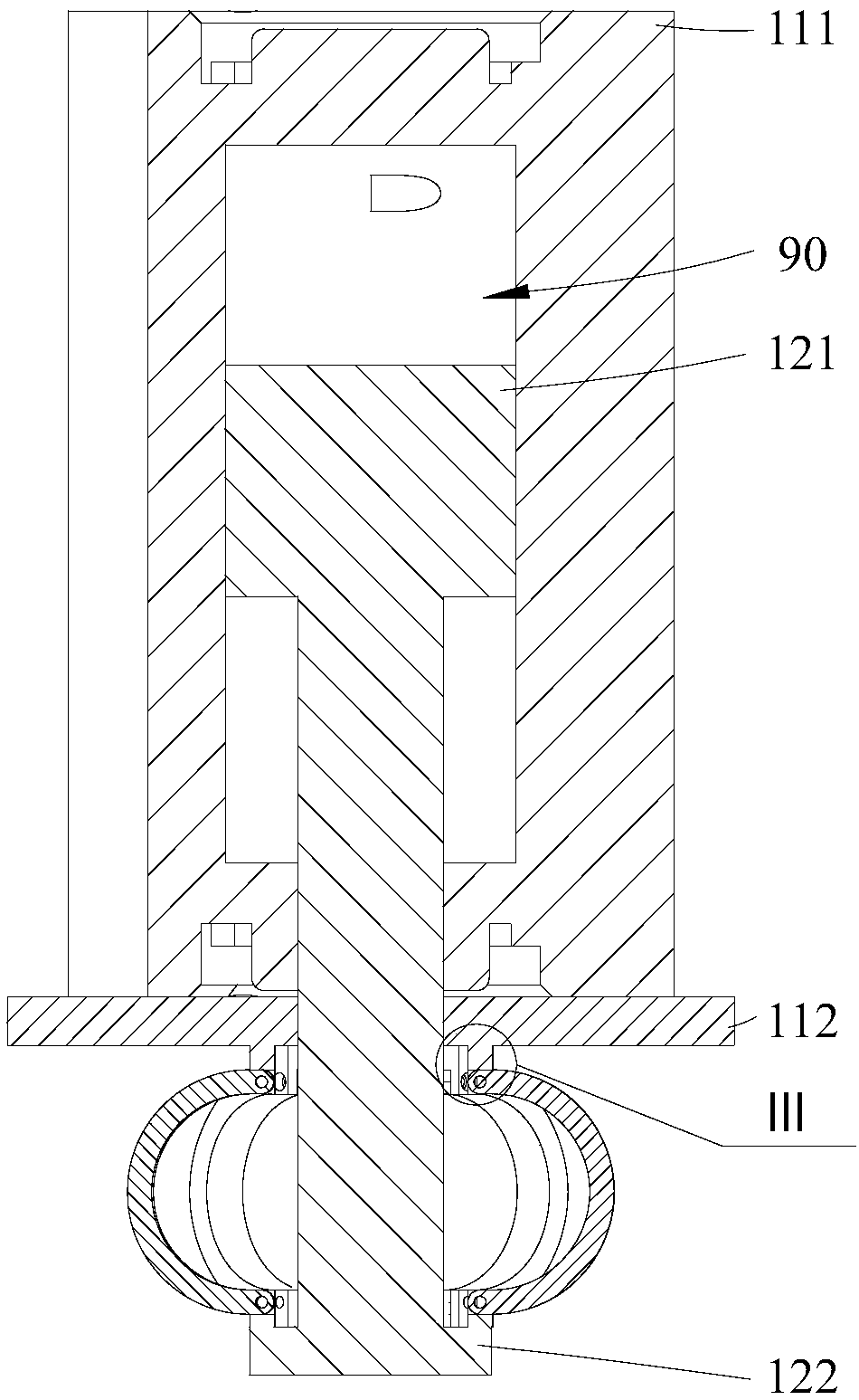
[0048] Please refer to figure 1 with figure 2 , figure 1 It shows the specific structure of the inner support fixture 10 in the first viewing angle in this embodiment. figure 2 It shows the specific structure of the inner brace fixture 10 in the second viewing angle in this embodiment.

[0049] The inner support fixture 10 includes a first base 11 , a second base 12 and a plurality of elastic pieces 13 .

[0050] Specifically, the second base body 12 is movably connected to the first base body 11 , and the second base body 12 is configured to reciprocate relative to the first base body 11 in a predetermined direction. The opposite ends of the plurality of elastic pieces 13 are respectively disposed on the first base 11 and the second base 12 . It should be noted that, in figure 1 The pointing in the preset direction is shown in .

[0051] ...

Embodiment 2

[0066] This embodiment provides an inner support fixture 20 , which meets the requirements of clamping and moving cavity-type parts.

[0067] Please refer to Figure 4 and Figure 5 , Figure 4 The specific structure of the inner brace fixture 20 in the first viewing angle in this embodiment is shown. Figure 5 It shows the specific structure of the inner support fixture 20 in the second viewing angle in this embodiment. In this embodiment, the inner support fixture 20 is substantially the same as the inner support fixture 10 provided in the above-mentioned embodiment 1, except that the inner support fixture 20 provided in this embodiment further includes a spacer 21, and the spacer 21 The ring is arranged on the outer wall of the second base 12, and the spacer 21 is set around to ensure that when the second base 12 moves relative to the first base 11, that is, when the second base 12 moves relative to the first base 11, that is, when the second base 12 is compressed, the e...

Embodiment 3

[0069] This embodiment provides an inner support jig 30 , which meets the requirements of clamping and moving cavity-type parts.

[0070] Please refer to Image 6 , Image 6 The specific structure of the inner support clamp 30 in this embodiment is shown.

[0071] In this embodiment, the inner support fixture 30 is substantially the same as the inner support fixture 10 provided in the above-mentioned embodiment 1. The projection of the axis on the radial direction of the annular array of a plurality of shrapnel 13 is the first projection, and the projection of the defined shrapnel 13 in the radial direction of the annular array of a plurality of shrapnel 13 is the second projection, and the first projection is the same as the second projection. The projections have an included angle between them. That is, it can be explained that, combined with Image 6 , it can be seen that the positional relationship of the elastic pieces 13 in the inner support fixture 30 is different f...


PUM


Abstract

The invention discloses an internal support clamp and a clamping device and relates to the technical field of clamps. The internal support clamp comprises a first base, a second base and a plurality of elastic pieces, wherein the second base is structured to move reciprocatingly relative to the first base in a reset direction; both ends of the plurality of elastic pieces are arranged on the firstbase and the second base respectively; the plurality of elastic pieces are structured to deform and expand and are supported onto the inner wall of the cavity of a cavity type part when the second base moves to the first base in the preset direction, so that the internal support clamp can maintain the relative position relation with the clamped cavity type part. The internal support clamp can meetthe requirements on clamping and moving the cavity type part.

Description

technical field [0001] The present invention relates to the technical field of clamps, in particular to an internal support clamp and a clamping device. Background technique [0002] Currently used fixtures, such as traditional cylinder jaws, rubber, silicone airbags, etc., cannot meet the needs of clamping and moving for cavity parts. Contents of the invention [0003] The first object of the present invention is to provide an inner support fixture, which meets the requirements of clamping and moving cavity-type parts. [0004] A second object of the present invention is to provide a clamping device capable of effectively clamping and moving cavity type parts. [0005] Embodiments of the present invention are achieved like this: [0006] An inner support fixture is used for clamping cavity-type parts, including a first base body, a second base body and a shrapnel, the second base body is movably connected to the first base body, and the second base body is configured to...

Claims


Application Information

Patent Timeline
Patent Type & Authority Applications(China)
IPC IPC(8): B25J15/00B25J15/12
CPCB25J15/0047B25J15/12
Inventor 鲍磊许娜单雪梅
Owner BEIJING SOFT ROBOT TECH CO LTD
Why Eureka
Try Eureka