Carpentry tool

a carpentry and tool technology, applied in the field of carpentry tools, can solve the problems of difficult installation of hidden fasteners in the edge or side of the board and the underlying joist, difficult to achieve, and many conventional tools of the type described above are complex and expensive, so as to achieve the effect of effectively pushing the board and enhancing access and use of the tool

Active Publication Date: 2015-12-03
NAT NAIL
View PDF10 Cites 8 Cited by
  • Summary
  • Abstract
  • Description
  • Claims
  • Application Information

AI Technical Summary

Benefits of technology

[0006]In one embodiment, the primary cam can be in the form of a pusher cam and the secondary cam can be in the form of a joist cam. The joist cam and the other joist engagement element can lay opposite one another, across an aperture configured to receive a joist, also referred to as a joist recess. Operation of the pusher cam to engage a board and move it can result in rotation and / or movement of the joist cam so that the joist cam and the other joist engaging element dynamically grip and / or bite into an underlying joist or substructure, optionally to prevent the tool from slipping or moving away from the board being pushed by the pusher cam.
[0017]The current embodiments of the carpentry tool herein provide a simple and effective device that can be used to dynamically push and place boards, over joists, flooring and other substrates. The tool can be operated one handed so that a user is free to utilize another hand to install a fastener while a board is being pushed with the tool. Where the tool includes a lock element, or where the pusher cam and lever are fully rotated, both the user's hands can be free while the tool holds a board. Thus, the user can use both hands to install a fastener while the tool holds the board in a desired configuration. The tool also is able to fit different size joists yet still effectively lock the base and remainder of tool in fixed relation to the same as the pusher cam engages a board. The tool can provide variable clamping to effectively clamp or grip a joist and provide a solid foundation for pushing the board using the pusher cam. With the lock, and the configuration of the pusher cam relative to the base, a user can lock the pusher cam in a number of positions to provide a gap of various dimensions between adjacent boards. This can provide significant gap variability. Further, when the joist cam and secondary joist engaging element are included, these components can effectively lock the base and remainder of the tool in a relatively fixed position to prevent rocking of the tool when forces are applied to the pusher cam and the board being pushed.

Problems solved by technology

Where a gap between boards is desired, it may be hard to achieve.
Thus, hidden fasteners can be difficult to install in the edge or side of the board and underlying joist.
Many conventional tools of the type described above are complex and expensive.

Method used


Image

  • Carpentry tool
  • Carpentry tool
  • Carpentry tool

Examples


Embodiment Construction

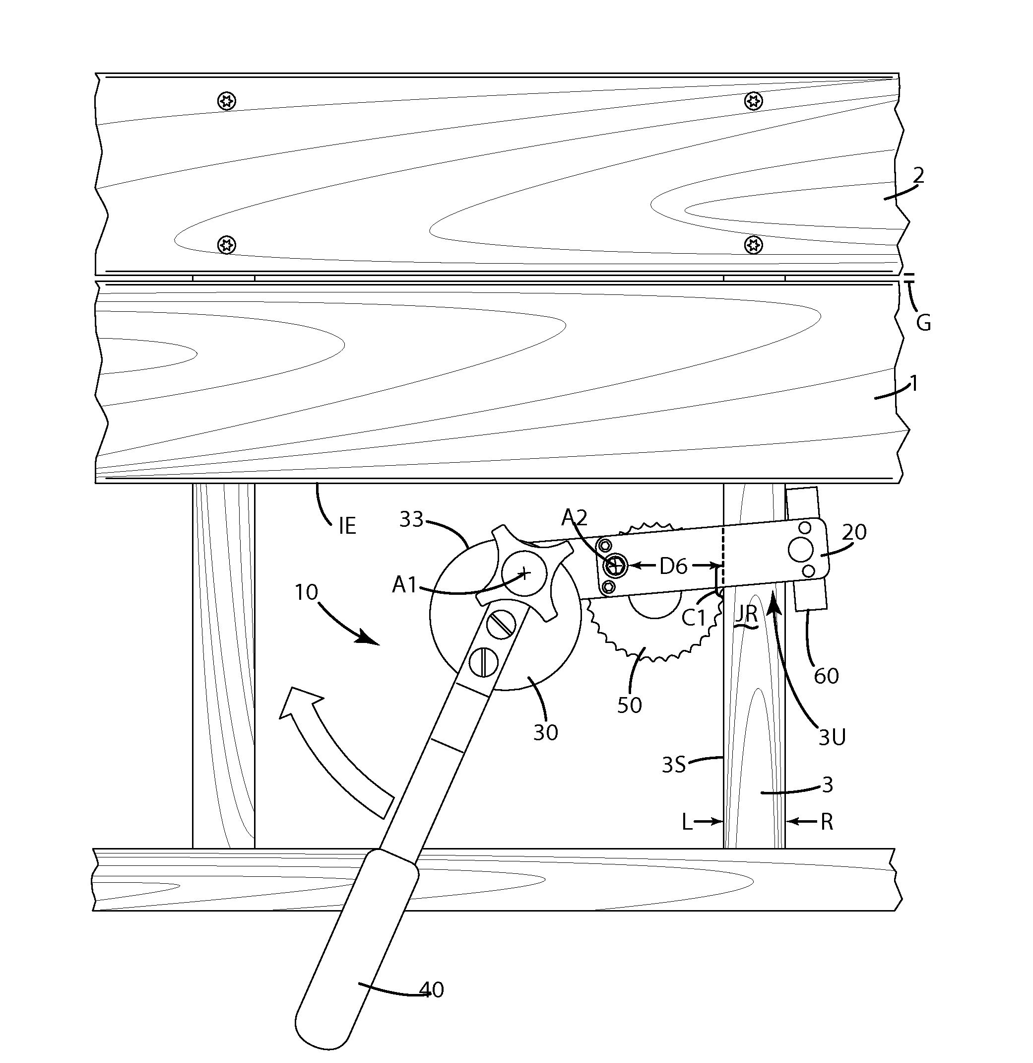
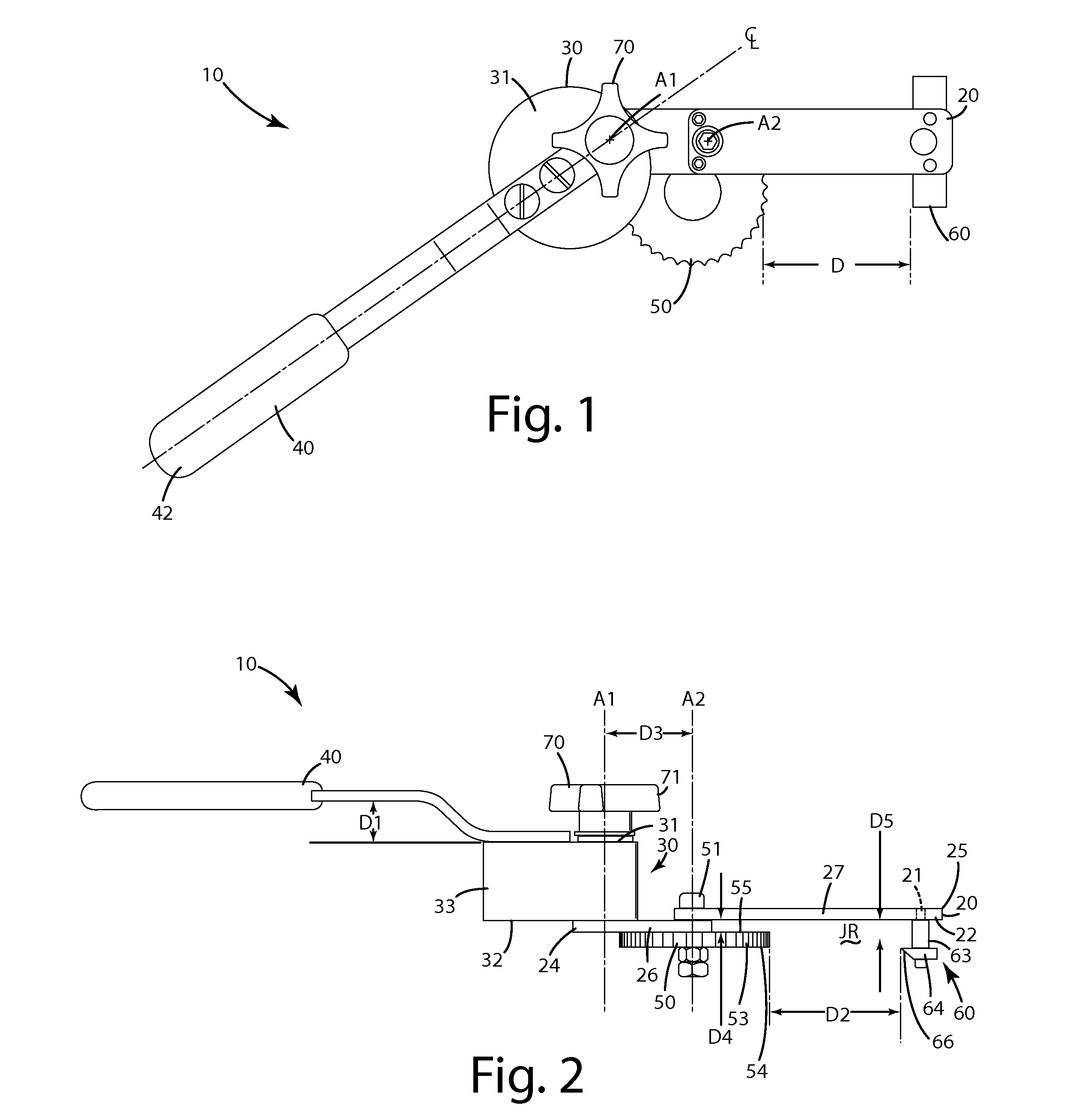
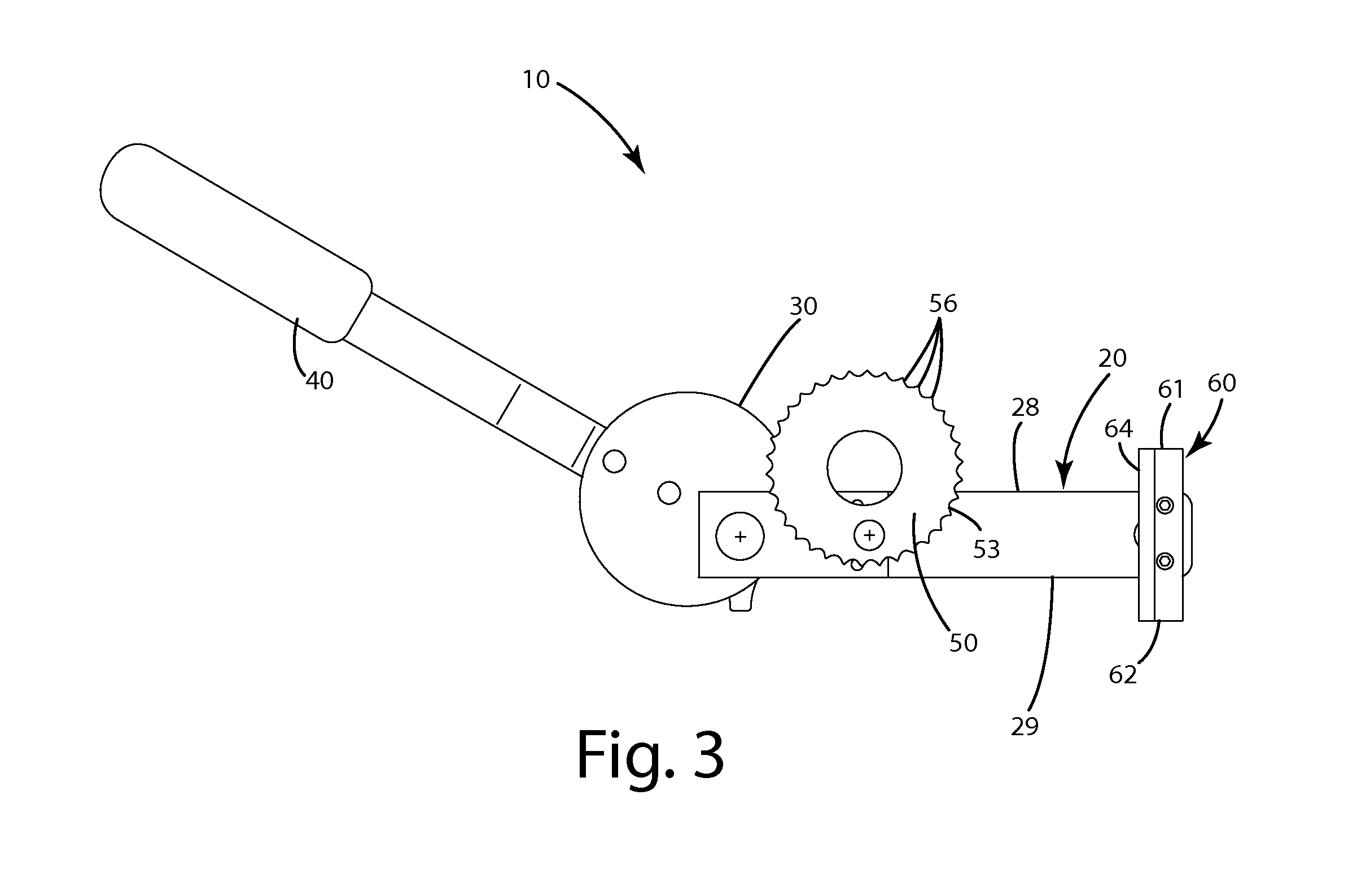
[0036]A carpentry tool according to a current embodiment is illustrated in FIGS. 1-3 and generally designated 10. The carpentry tool can include a base 20 to which a pusher cam 30 is attached. A lever 40 can be attached to the pusher cam. A joist cam 50 can be joined with the base 20, opposite a secondary joist engaging element 60, across a joist recess. The pusher cam 30 includes an outer perimeter that can be angled and / or rounded, but configured to engage a board to be pushed as further described below. The joist cam 50, also referred to as a first or primary joist engaging element, can be spaced a dynamically adjustable distance D from the secondary joist engaging element 60. This distance D can correspond to the width of one or more joists or underlying substructures.

[0037]Although referred to as a “cam” herein, the pusher cam and joist cam herein can be of a variety of different shapes and sizes. Generally, the axis of rotation of these elements is offset from the geometric an...


PUM


Abstract

A carpentry tool for pushing deck, flooring or other boards toward one another on a joist or underlying substructure. The tool can be operated with one hand, leaving the other hand free for installation of a fastener. The tool can leave an area adjacent the joist and board exposed so that a fastener can be installed in the board and joist in that area. The tool can include a pusher cam rotatably joined with a base, and fixedly joined with a lever. A joist cam and joist blade can be joined with the base, disposed opposite one another across a variable width joist recess. The pusher cam and joist cam can be mechanically coupled to the base so that rotation of the pusher cam urges rotation of the joist cam, thereby causing the joist cam to dynamically grip the joist and prevent the tool from rocking and / or moving away from the pushed board.

Description

BACKGROUND OF THE INVENTION[0001]The present invention relates to a carpentry tool and, more particularly, to a tool adapted to push or move parallel boards together in decks, flooring and other structures.[0002]There are many conventional tools utilized for pushing deck or flooring boards into parallel contact before nailing the boards to a joist. Such tools are illustrated in U.S. Pat. No. 5,826,858 to Gordon, U.S. Pat. No. 5,248,127 to Young and U.S. Pat. No. 5,269,494 to Pittman.[0003]Conventional tools have various drawbacks. Most are configured so that they push the boards immediately adjacent one another. Where a gap between boards is desired, it may be hard to achieve. Many tools cover a top of a joist immediately adjacent an outer edge of the board. Thus, hidden fasteners can be difficult to install in the edge or side of the board and underlying joist. Several tools require a user to use both hands to operate the tool, with another worker having to nail the boards to the u...

Claims


Application Information

Patent Timeline
Patent Type & Authority Applications(United States)
IPC IPC(8): E04F21/22
CPCE04F21/22B25B5/08E04F21/1855
Inventor VANDENBERG, ROGER A.
Owner NAT NAIL
Why Eureka
Try Eureka