Adjustable door threshold

a threshold and adjustment technology, applied in the field of door thresholds, can solve the problems of not being able to effectively address the desire for a single threshold, stock transition strips cannot account for the many variations in wall- and frame-depth, etc., to achieve the effect of effectively gripping the carpet, reducing the need for carpet tacks, and reducing the ease with which they are applied

Active Publication Date: 2012-05-29
RISSONE ROBERT
View PDF16 Cites 8 Cited by
  • Summary
  • Abstract
  • Description
  • Claims
  • Application Information

AI Technical Summary

Benefits of technology

[0003]Threshold 1 of FIG. 1 requires the presence of carpet tacks 5 and supports 7 therefor proximate to the overhangs 3 in order to fasten down the carpet 4 so as to prevent the carpet from slipping out from over the overhangs 3. However, if the carpet 4 wears out, or tears, tacks 5 tend to poke through the carpet and can be a hazard because they can injure feet of a person walking near the threshold.
[0004]FIG. 2 is a perspective view of a door threshold that reduces and / or eliminates the need for carpet tacks, thus representing an improvement over certain prior art systems. Thresholds of this type are disclosed in, for example, application Ser. No. 11 / 344,114, the entire content of which is hereby incorporated herein by reference. Threshold 10 may be of aluminum or the like. Threshold 10, on one or both sides thereof, includes upper and lower members, 12 and 14 respectively, which sandwich an end of carpet 4 therebetween. As shown in FIG. 2, carpet pad 6 may stop short of the lower member 14 so that only the carpet 4 is sandwiched between the upper and lower members 12 and 14 in certain embodiments (although this need not be the case in all embodiments). In certain embodiments, at least parts of the upper and lower members 12 and 14 are substantially parallel (i.e., parallel plus / minus about 20 degrees) to one another.
[0005]In certain embodiments, upper and / or lower member(s) 12, 14 grip or otherwise maintain the carpet 4 that is located therebetween. Thus, the need for carpet tacks proximate to the threshold is reduced and / or eliminated because the threshold itself maintains the end of the carpet in position and reduces the ease with which it may be pulled out from between members 12, 14. Overhang 12 may be flexible in certain embodiments, so as to provide a downward-directed biasing force against the carpet 4 to help maintain the end of the carpet between members 12 and 14. The threshold further allows for a variety of different carpet and / or pad thicknesses, and can maintain a slight rise above the carpet for a door sweep to seal against and yet not rub or significantly rub on the carpet when closing.
[0006]Carpeting 4 typically is glued down or stretched and held by carpet tack strips along the walls. At the door opening, the carpet cannot be glued to a pad typically. The carpet tuck feature of threshold 10 effectively grips the carpet and reduces the ease with which it may be pulled away from the threshold. The carpet will have been stretched and held at either side of the door opening.

Problems solved by technology

However, if the carpet 4 wears out, or tears, tacks 5 tend to poke through the carpet and can be a hazard because they can injure feet of a person walking near the threshold.
However, such stock transition strips do not account for the many variations in wall- and frame-depth.
For example, current thresholds are made to a specific depth dimension and, as such, cannot effectively address the desire to have a single stock threshold span the many variations in wall- and frame-depth.
Accordingly, many thresholds do not meet certain fire codes, some of which may require a true fire separation under the door and do not allow carpet-to-carpet detailing.

Method used


Image

  • Adjustable door threshold
  • Adjustable door threshold
  • Adjustable door threshold

Examples


Embodiment Construction

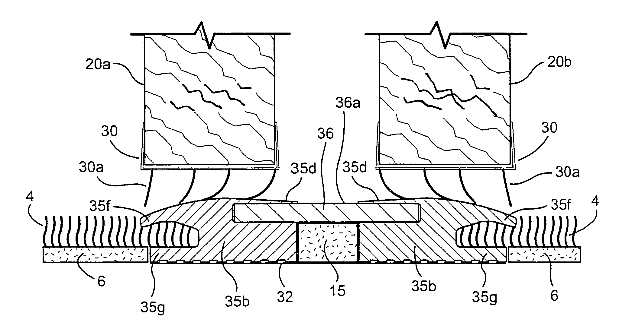
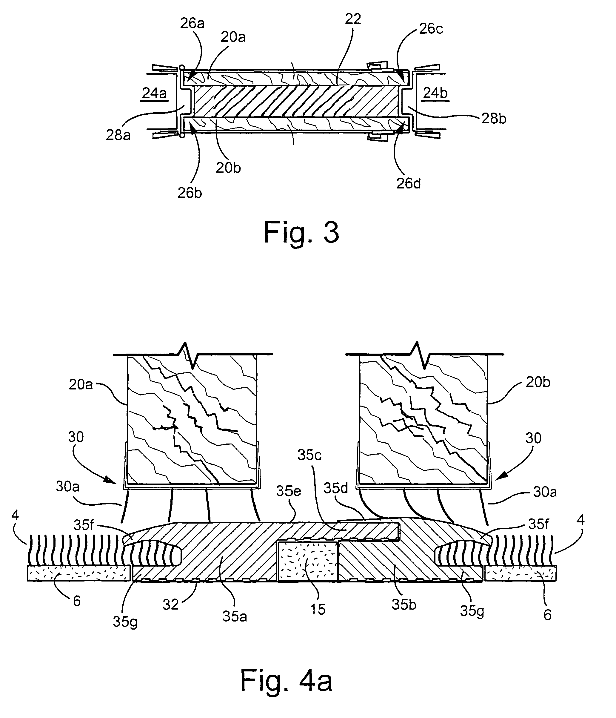
[0032]Referring now more particularly to the drawings in which like reference numerals indicate like parts throughout the several views, FIG. 4a is a perspective view of an adjustable threshold having a male-female connector, in accordance with an example embodiment. As shown in FIG. 4a, the adjustable threshold is positioned under two doors 20a-b which may be, for example, a fire door and a non-fire rated door, respectively. Of course, it will be appreciated that either, both, or neither door need be a fire door. Top portion 35e of the adjustable threshold is located between doors 20a-b, and corresponds to the viewable portion of threshold 22 shown in FIG. 3.

[0033]The heights of doors 20a-b optionally may be adjustable, for example, via adjustment mechanisms 30. Also, brushes (or sweep) 30a optionally may be located at the bottom of doors 20a-b and project downwards towards the adjustable threshold, for example, to at least partially seal (e.g. provide insulation, protection, separ...


PUM

PropertyMeasurementUnit
sizeaaaaaaaaaa
heightaaaaaaaaaa
thresholdaaaaaaaaaa

Abstract

A door threshold may comprise a main body formed from two feet. In certain example embodiments, a male-female connection between the feet may be used to adjust the depth of the door threshold. In certain other example embodiments, a center bridge insert to be used in connection with two female feet to adjust the depth of the door threshold. In still further example embodiments, one or more center layers may be disposed between two feet, with the size of the center layer(s) determining the depth of the door threshold. Also, the door threshold may include upper and lower members for sandwiching carpet and / or carpet padding therebetween which, in certain example embodiments, may grip the carpet to reduce the ease with which it may be pulled out from between the upper and lower members. Thus, certain example embodiments may reduce and / or eliminate the need for tacks proximate to the threshold.

Description

FIELD OF THE INVENTION[0001]Certain example embodiments of this invention relate a door threshold. More particularly, certain example embodiments of this invention relate to a door threshold that permits certain installation sequencing / issues to be controlled in varying degrees, addresses issues of security, and / or allows for improved practical uses. Door thresholds according to certain example embodiments of this invention may be used in the context of fire doors or any other suitable door application.BACKGROUND AND SUMMARY OF EXAMPLE EMBODIMENTS OF THE INVENTION[0002]FIG. 1 illustrates a known door threshold. In FIG. 1, threshold 1 serves as a carpet divider, is located under the door, and includes at least one overhang 3 under which carpet 4 and carpet pad 6 may be run. The FIG. 1 threshold is typically made of aluminum.[0003]Threshold 1 of FIG. 1 requires the presence of carpet tacks 5 and supports 7 therefor proximate to the overhangs 3 in order to fasten down the carpet 4 so a...

Claims


Application Information

Patent Timeline
Patent Type & Authority Patents(United States)
IPC IPC(8): E06B1/04E04C2/38E06B1/70
CPCE06B7/2316E06B1/70
Inventor RISSONE, ROBERT
Owner RISSONE ROBERT
Why Eureka
Try Eureka