
A hole opening device for gas pipeline and monitoring method thereof

A technology for gas pipelines and equipment, which is applied in the field of opening equipment for gas pipelines and its monitoring, achieving the effects of low cost of improvement, small hardware changes, and easy popularization and application

Active Publication Date: 2019-12-13
BEIJING GAS GRP
View PDF5 Cites 0 Cited by
  • Summary
  • Abstract
  • Description
  • Claims
  • Application Information

AI Technical Summary

Problems solved by technology

[0004] In order to overcome the problem that the existing technology cannot completely solve the problem of unauthorized use of the drilling machine for gas pipelines, the present invention innovatively provides a drilling equipment for gas pipelines and a monitoring method thereof. Through the research and development of intelligent drilling equipment, the present invention The state of the drilling machine for gas pipelines can be monitored in real time, and when the drilling machine for gas pipelines is in an unreasonable use state, the present invention can promptly notify the monitoring personnel of the situation, thereby effectively avoiding the failure of the drilling machine for gas pipelines. The problem of private use, and can obtain the evidence of the private use of the drilling machine, so as to completely avoid the problem of unauthorized use of the drilling machine for gas pipelines

Method used


Image

  • A hole opening device for gas pipeline and monitoring method thereof
  • A hole opening device for gas pipeline and monitoring method thereof

Examples


Embodiment 1

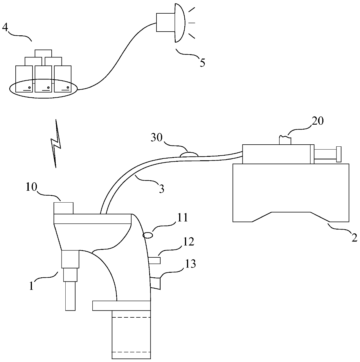
[0027] Such as figure 1 As shown, this embodiment specifically provides a gas pipeline drilling device with a monitoring function. The drilling device includes a drilling machine 1, a hydraulic station 2 and a hydraulic pipe 3, and the two ends of the hydraulic pipe 3 are respectively connected to the opening Machine 1 and hydraulic station 2, the driving form of drilling machine 1 is hydraulic drive, the power source comes from hydraulic station 2, and hydraulic station 2 provides power for drilling machine 1 to drive the drilling rod of drilling machine 1 to move in the circumferential direction, And control the rotating speed and the direction of the drilling rod of the hole tapping machine; Microcontroller 10, vibration sensor 11, level sensor 12 and Beidou positioning module 13 are also fixed, accelerometer 20 is fixed on hydraulic station 2, pressure sensor 30 is fixed on hydraulic pipe 3; vibration sensor 11, level sensor 12, Beidou The positioning module 13 , the pres...

Embodiment 2

[0030] Based on the same inventive concept as Embodiment 1, this embodiment specifically discloses the monitoring method of the opening equipment for gas pipelines in Embodiment 1. Specifically, the monitoring method includes the following steps, such as figure 1 shown.

[0031] Step 1, the vibration signal of the vibration sensor 11, the angle signal of the level sensor 12, the positioning signal of the Beidou positioning module 13, the pressure signal of the pressure sensor 30 and the acceleration of the accelerometer 20 can be collected by the microcontroller 10 on the drilling machine 1 One or more signals in the signal, and the collected signal is sent to the server 4; in the present embodiment, the microcontroller 10 on the drilling machine 1 can perform information collection actions at preset time intervals, and the preset time can be Set as needed, for example, set to 3min or 30min.

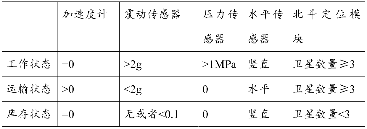
[0032] Step 2, identify the collected signal through the server 4 to obtain the ide...


PUM


Abstract

The invention discloses a perforating device for gas pipeline and a monitoring method thereof. The device comprises a perforating machine, a hydraulic station and a hydraulic pipe. A microcontroller,a vibration sensor, a horizontal sensor and a Beidou positioning module are fixed on the perforating machine, an accelerometer is fixed on the hydraulic station, and a pressure sensor is fixed on thehydraulic pipe. The monitoring method comprises the following steps: 1. Collecting vibration signals, angle signals, positioning signals, pressure signals and acceleration signals, and sending the collected signals to the server; 2, identifying the collected signal, and comparing the identifying result information with the filing information in the server; If so, returning to step 1; If not, step3 is performed; Step 3: Remind the monitoring staff to pay attention. The invention can timely determine the state of the hole-opening device, thereby effectively judging whether the hole-opening device is embezzled or not, and reminding the monitoring personnel in the case of embezzled.

Description

technical field [0001] The invention relates to the technical field of drilling equipment, more specifically, the invention relates to a drilling equipment for a gas pipeline and a monitoring method thereof. Background technique [0002] At present, in order to realize gas pipeline drilling, gas pipeline drilling machines are commonly used equipment in the field of gas pipelines; generally speaking, the cost of gas pipeline drilling machines is relatively high, and the cost of use is also relatively high. During the actual use of the drilling machine, it was found that there were employees who took the drilling machine for the unit's gas pipeline to use elsewhere without the permission of the unit (enterprise or company). This behavior would add huge costs to the company and cause Big loss. Although the existing technology has added an equipment management mechanism, clarified the rules for the use of the drilling machine, and strictly required employees to use the drilling...

Claims


Application Information

Patent Timeline
Patent Type & Authority Patents(China)
IPC IPC(8): B26D7/00B26F1/16G05B19/042G01D21/02
CPCB26D7/00B26F1/165G01D21/02G05B19/042
Inventor 焦建瑛王嵩梅张涛齐晓琳马瑞莉崔涛车陈新王博何英杰徐嘉
Owner BEIJING GAS GRP
Learn More