Method for rapidly judging phase of electric-controlled engine system

An electronically controlled engine and system phase technology, applied in engine control, machine/engine, electrical control, etc., can solve problems such as long judgment time and prolong engine start-up time, and achieve low cost, reduced start-up time, and less hardware changes. Effect

Active Publication Date: 2011-04-06
CHERY AUTOMOBILE CO LTD
View PDF0 Cites 0 Cited by
  • Summary
  • Abstract
  • Description
  • Claims
  • Application Information

AI Technical Summary

Problems solved by technology

[0003] However, the above-mentioned method of judging the phase by relying on the level of the single tooth signal of the camshaft and the missing tooth signal of the crankshaft has at most two chances to judge the phase within 720 degrees of the crankshaft angle, and the judgment time is too long, thus prolonging the engine start-up time

Method used


Image

  • Method for rapidly judging phase of electric-controlled engine system
  • Method for rapidly judging phase of electric-controlled engine system
  • Method for rapidly judging phase of electric-controlled engine system

Examples


Embodiment 1

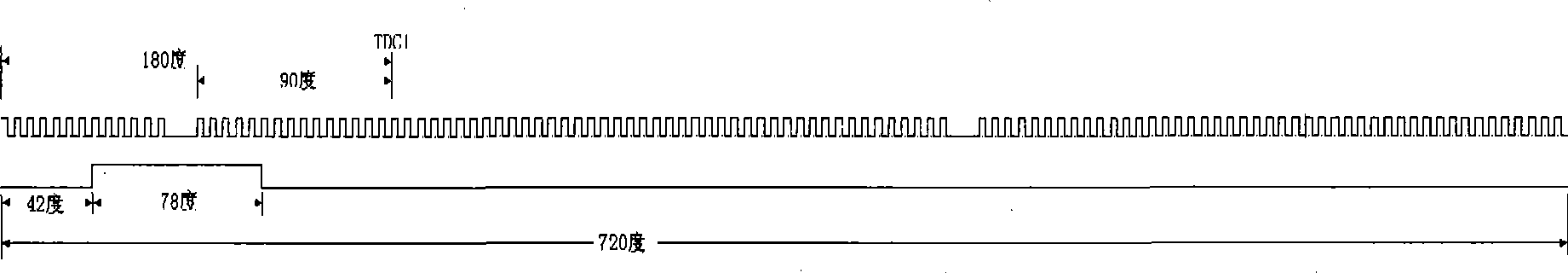
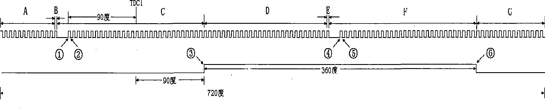
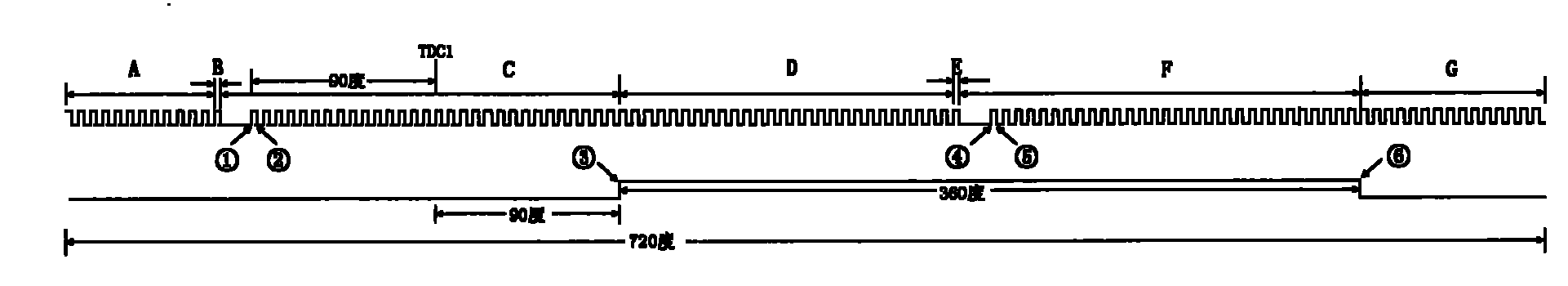
[0038] Such as figure 2 As shown, the crankshaft signal wheel of the electronically controlled engine in this embodiment has 58 teeth in total, and the width of the missing tooth set in the scope of the single tooth signal corresponding to the camshaft signal wheel of the crankshaft signal wheel is 2 times of the normal tooth interval. times. That is, the entire crankshaft signal wheel has 60 teeth with equal intervals, and two adjacent teeth are removed within the range corresponding to the single-tooth signal of the camshaft signal wheel, that is, 58 normal teeth, and two teeth are missing. The crankshaft rotation angle corresponding to the tooth width of the camshaft signal is 360 degrees, the starting position of the camshaft tooth profile signal corresponds to the 90 degree crankshaft angle after the compression top dead center of the first cylinder, and 180 degrees before the starting position of the camshaft tooth profile signal The end position of the crankshaft miss...


PUM


Abstract

The aim of the invention is to provide a method for quickly determining the system phase of an electrically controlled engine. The key points of the method include: an engine crankshaft is provided with a crankshaft signal wheel with equidistant multi-tooth structure and a cam shaft is provided with a cam shaft signal wheel with single-tooth structure. Corresponding to the range of the single-tooth signal of the cam shaft signal wheel, the crankshaft signal wheel is provided with a missing-tooth, of which the width is an integral multiple of the normal tooth distance. An electrically controlled unit of the engine can determine the system phase of the engine by detecting a rising edge and a descending edge of the tooth signal of the cam shaft signal wheel, and the corresponding relation ship between rising edges of the missing-tooth signal of the crankshaft signal wheel and electrical levels of the signal of the cam shaft signal wheel. The method has the advantages of determining the system phase of the engine in a short time, reducing the starting time of the engine and simultaneously less modifying the hardware of the engine, along with low cost and suitability for popularizationand application.

Description

technical field [0001] The invention belongs to the technical field of control of electronically controlled engines, and in particular relates to a method for judging system phases in the technical field of electronically controlled engines. Background technique [0002] In the working process of the electronically controlled engine, it is necessary to accurately determine the phase relationship between the camshaft and the crankshaft, so as to correctly control the opening and closing of the intake and exhaust valves of each cylinder and perform fuel injection or spark plug ignition. In the working cycle, the crankshaft rotates twice and the camshaft rotates once, so the phase relationship between the crankshaft and the camshaft is not one-to-one correspondence. At present, the phase detection of electronically controlled engines mainly adopts the following method: the crankshaft signal wheel adopts a 60-2 tooth structure, that is, the entire crankshaft signal wheel ring ge...

Claims


Application Information

Patent Timeline
Patent Type & Authority Patents(China)
IPC IPC(8): F02D41/06
Inventor 苏万樯
Owner CHERY AUTOMOBILE CO LTD
Why Eureka
Try Eureka