
Portable intelligent stamping control machine

A printing control machine, portable technology, applied in the field of seals, can solve the problems of inconvenient movement, printing control machine stains, printing control machine volume, etc., to achieve flexible and convenient use, prevent printing oil leakage, and avoid seal stealing operations

Pending Publication Date: 2018-11-27
HANGZHOU RIMEI KAIKAI ELECTRONICS TECH CO LTD
View PDF0 Cites 2 Cited by
  • Summary
  • Abstract
  • Description
  • Claims
  • Application Information

AI Technical Summary

Problems solved by technology

In the past, the printing control machine was generally large in size. If it needs to be used in a different location, it will be inconvenient to move, and it is inconvenient to carry out; the printing control machine is easy to cause stains when filling oil, and there is a defect of printing oil leakage; when stamping , especially when stamping the seam seal, due to the fixed setting of the stamp, there will be defects that the stamp is not clear due to the uneven surface of the stamp. There are defects of poor clarity and uniformity when covering the seam stamp; in addition, the use safety of the existing printing control machine needs to be further improved

Method used


Image

  • Portable intelligent stamping control machine
  • Portable intelligent stamping control machine
  • Portable intelligent stamping control machine

Examples


Embodiment Construction

[0028] The present invention will be further described below in conjunction with the accompanying drawings and specific embodiments, but the scope of protection of the present invention is not limited thereto.

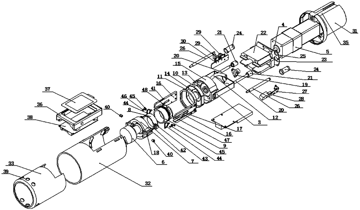
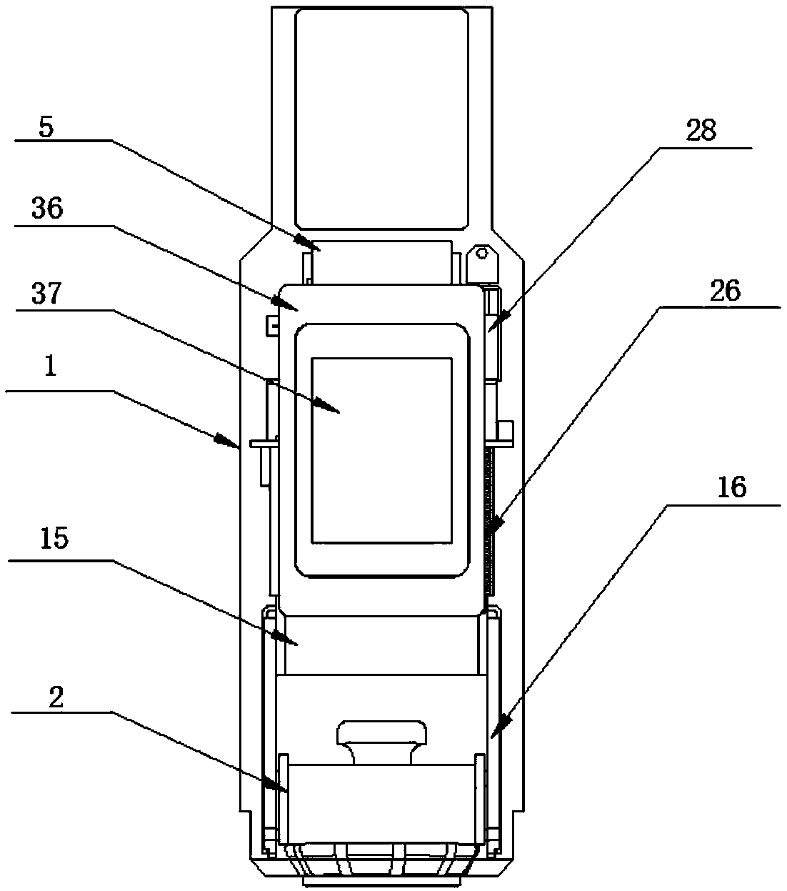
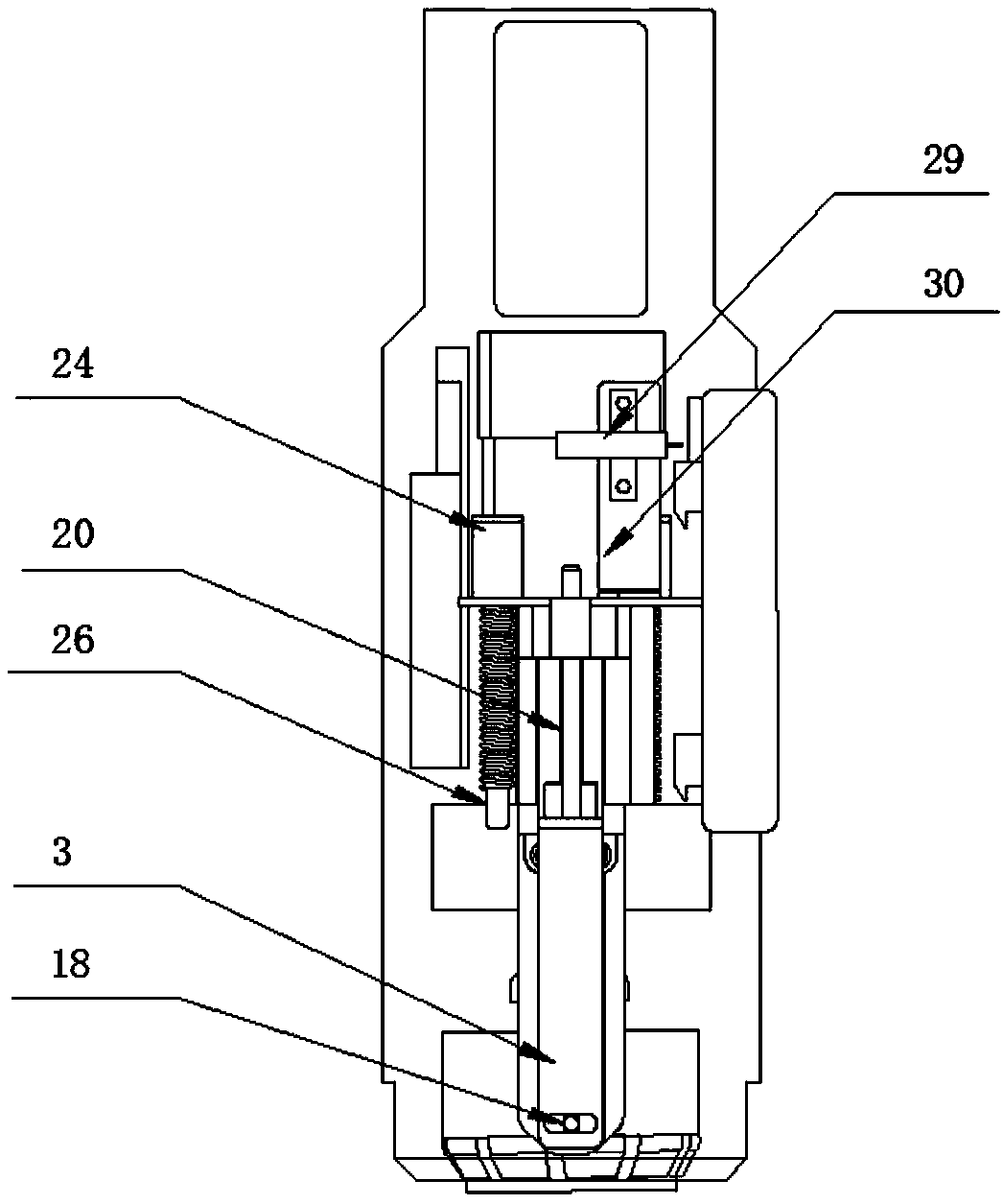
[0029] refer to Figure 1-9 ; A portable intelligent printing control machine, which includes a sleeve-type housing 1 with a display screen, a stamp mechanism 2 and a guide bracket 3, and a screw 4 is arranged inside the sleeve-type housing with a display screen, and the screw rod 4 is driven by a drive motor 5; the stamp mechanism includes a stamp 6, a chapter frame 7 and a chapter cover 8, the stamp 6 is arranged in the chapter cover 8 through the chapter cover inner ring 9, and the chapter cover 8 is installed on the chapter frame 7 On the one hand, the seal is convenient for authorized personnel to disassemble and assemble, and at the same time, it can prevent unauthorized personnel from stealing the seal. An ink pad box 10 is provided above the chapter frame 7, a...


PUM


Abstract

The invention relates to a portable intelligent stamping control machine. The stamping control machine comprises a sleeve type casing with a display screen, a stamping mechanism and a guide bracket. The stamping mechanism comprises a stamp, a stamp frame and a stamp sleeve, an inkpad box is arranged above the stamp frame, and the lower portion of the inkpad box is provided with an inkpad retainerring. The top of the inkpad box is provided with an injection port communicated with a through pipe for injecting stamp-pad ink, and the injection port is communicated with a guide groove in the middle of the inkpad box. The guide bracket is provided with a stamp frame rail provided with 'Omega'-shaped hollow track, and the stamp frame is connected to the hollow track through a rotating shaft. A screw bracket for mounting a screw is arranged at the middle position of the top of the guide bracket, and guide pins are symmetrically arranged on both sides of the screw bracket. Linear bearings arearranged at the tops of the guide pins, and guide grooves are formed around the guide pins. The stamping control machine occupies small space, and is more flexible and convenient to use. The stamp-padink does not leak, the stamping is more precise and clear, the stamp safety can be effectively guaranteed, and the phenomena of stealing and losing stamps and the like can be effectively avoided.

Description

technical field [0001] The invention belongs to the technical field of seals, and in particular relates to a portable intelligent printing control machine. Background technique [0002] At present, in many industries, signing or sealing is manually managed by managers, and the use of seals is also carried out in an open environment. [0003] With the continuous development of the mechanical field, more and more manual operations are mechanized. The printing control machine can replace people's manual stamping. The printing control machine is widely used as office equipment, and the frequency of use is also high, especially in the financial industry, such as banks and tax authorities. In the past, the printing control machine was generally large in size. If it needs to be used in a different location, it will be inconvenient to move, and it is inconvenient to carry out; the printing control machine is easy to cause stains when filling oil, and there is a defect of printing o...

Claims


Application Information

Patent Timeline
Patent Type & Authority Applications(China)
IPC IPC(8): B41K3/04B41K3/62
CPCB41K3/04B41K3/62
Inventor 龚苗苗柴淑贤龚昌开
Owner HANGZHOU RIMEI KAIKAI ELECTRONICS TECH CO LTD
Learn More