Commutator with reinforcing ring
A technology of reinforcing ring and metal ring, applied in the field of commutator, can solve problems such as damage to the reinforcing ring, and achieve the effects of reducing production cost, preventing tilting, and improving torsional strength
- Summary
- Abstract
- Description
- Claims
- Application Information
AI Technical Summary
Problems solved by technology
Method used
Image

Examples
Embodiment Construction
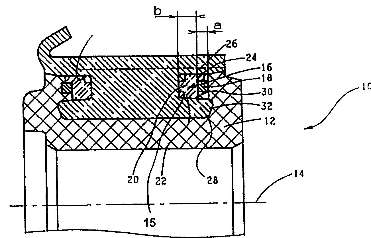
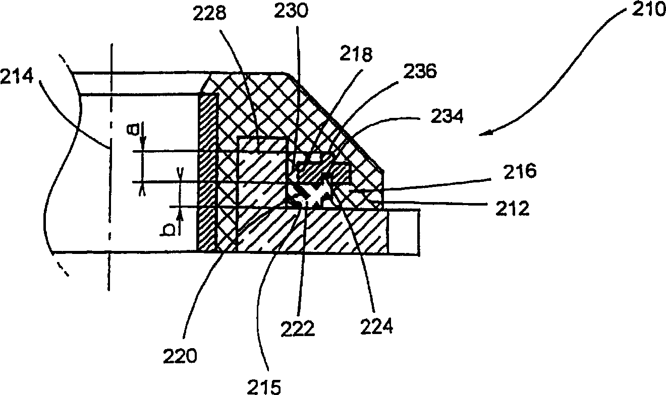
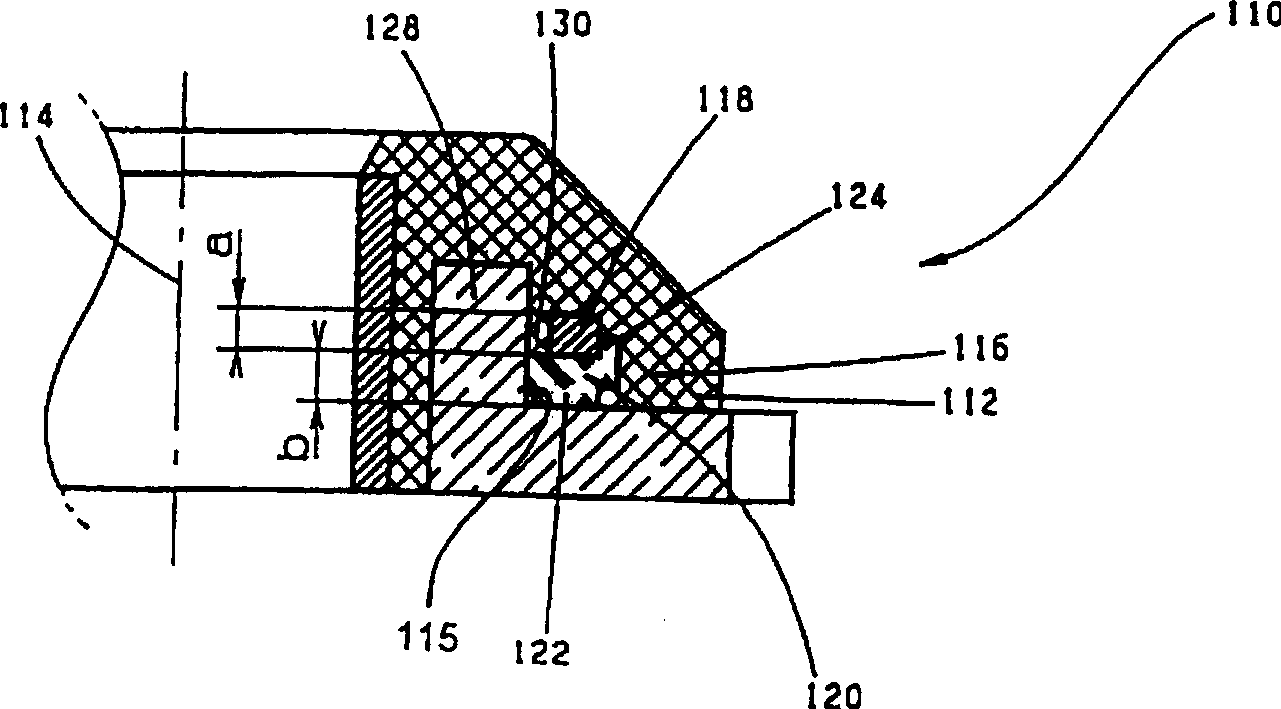
[0030] figure 1 A partial cross-section of a commutator 10 is shown, the copper section 26 of which is cast or embedded in the plastic 12 and which is rotatable about the axis of rotation 14 when the commutator 10 is in operation.
[0031] In order to increase the torsional strength, the commutator 10 is provided with a reinforcing ring 16 at least on one end face, preferably on both end faces, which consists of a metal ring 18 and an insulating ring 20 . The reinforcement ring 16 is mounted in a mounting seat 15 in a copper segment 26 . In this embodiment, the receptacle 15 is groove-shaped and is formed by cutouts in the copper segments 26 . Although there are various embodiments for insulating rings of this type, fiberglass rings 20 are preferably used as insulating rings.
[0032] On its side facing the axis of rotation 14 , the copper section 26 has a holding core 28 which forms part of the mounting seat 15 of the reinforcement ring 16 .
[0033] Depend on figure 1 It...
PUM
 Abstract
Description
Claims
Application Information
 - Generate Ideas
- Intellectual Property
- Life Sciences
- Materials
- Tech Scout
- Unparalleled Data Quality
- Higher Quality Content
- 60% Fewer Hallucinations
Browse by: Latest US Patents, China's latest patents, Technical Efficacy Thesaurus, Application Domain, Technology Topic, Popular Technical Reports.
© 2025 PatSnap. All rights reserved.Legal|Privacy policy|Modern Slavery Act Transparency Statement|Sitemap|About US| Contact US: help@patsnap.com