
Cord fabric winding device

A technology of curtain fabric and curtain fabric, which is applied in door/window protection devices, anti-glare equipment, transportation and packaging, etc., can solve the problems of high layout space requirements, inability to guarantee mechanical strength, increased diameter and size, etc., and achieve a good deployment effect. , The effect of improving storage capacity and expanding size

Pending Publication Date: 2018-11-27
浙江智动汽车部件有限公司
View PDF0 Cites 0 Cited by
  • Summary
  • Abstract
  • Description
  • Claims
  • Application Information

AI Technical Summary

Problems solved by technology

[0003] However, in the existing cord retracting device, since the cord is wound on a single reel, for a cord of a general size, the reel cannot be too thin, otherwise it needs to be rotated many times when opening and retracting the cord, and its mechanical strength cannot be guaranteed. When the cord is retracted, the diameter of the reel after winding is also greatly increased. In addition to the metal shell, the entire retracting device takes up a lot of space, and the requirements for the layout space are relatively high, especially it is difficult to install in a small space such as a car. Install and use

Method used


Image

  • Cord fabric winding device
  • Cord fabric winding device
  • Cord fabric winding device

Examples


Embodiment 1

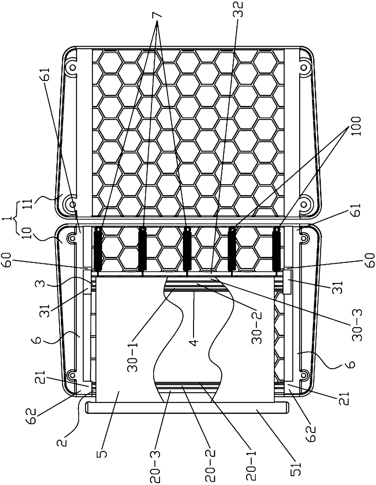
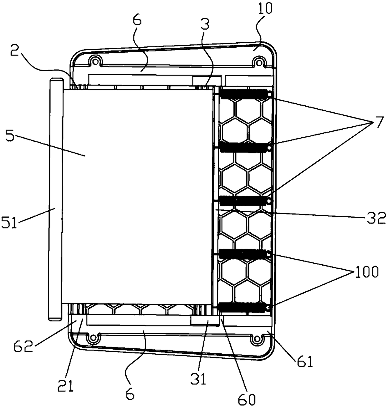
[0041] see Figure 1-5 , the cord retracting device of this embodiment includes a housing 1, a fixed retractor 2, a moving retractor 3, a retracting rod 4, a cord 5, two slide grooves 6 and at least two return springs 7, and N is equal to 3.

[0042] The shell 1 is a quadrangular flat box-shaped structure, and a curtain outlet is opened on one side thereof. Specifically, the casing 1 is composed of a box body 10 and a box cover 11 that is arranged on the box body 10, and the outlet of the curtain is opened on the box body 10 or between the box body 10 and the box cover 11. The shell 1 is injection molded.

[0043] In order to facilitate disassembly and maintenance, the box body 10 and the box cover 11 are connected by screws or buckle structures.

[0044] In order to improve the mechanical strength of the casing 1 , regular hexagonal grid ribs are provided on the bottom of the box body 10 , and regular hexagonal grid ribs are also provided on the inner side of the box cover...

Embodiment 2

[0066] The cord retracting device of this embodiment is basically the same as that of Embodiment 1, the difference is that:

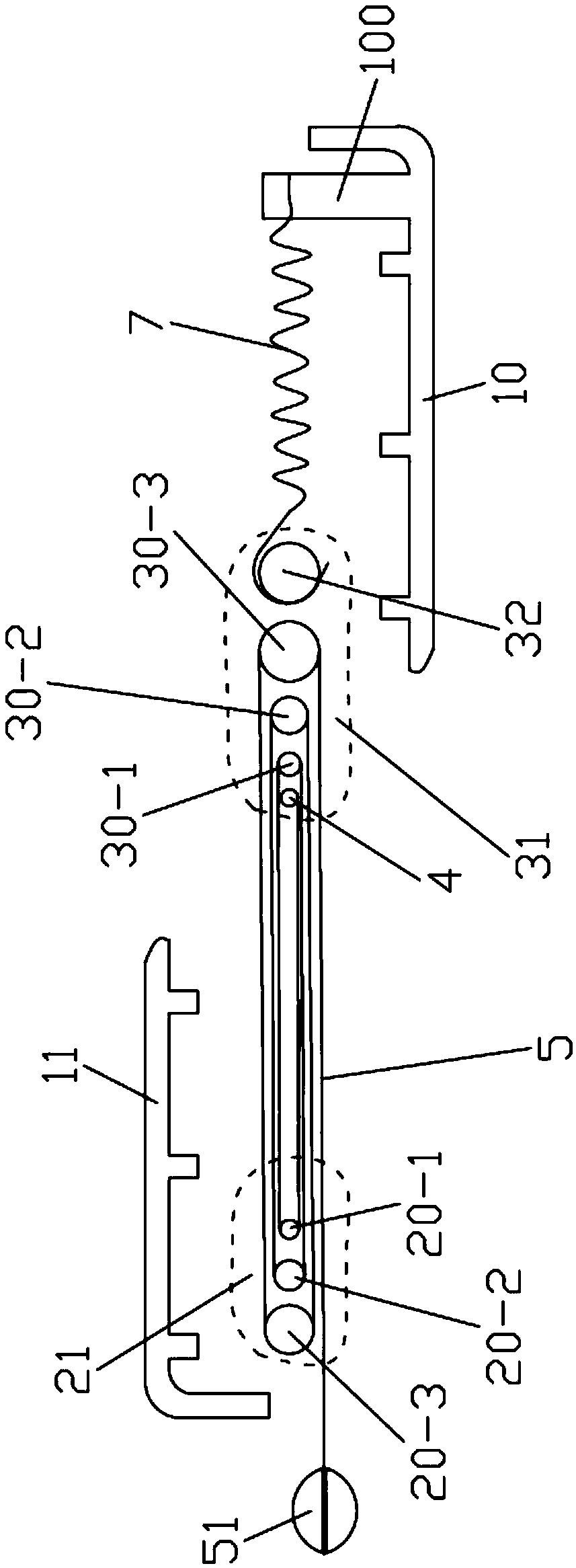
[0067] Such as Image 6 As shown, starting from the winding end, the cord 5 is wound around No. 1 moving roller 30-1, No. 1 fixed roller 20-1, No. 2 moving roller 30-2, No. 2 fixed roller Shaft 20-2, No. 3 moving roller 30-3 and No. 3 fixed roller 20-3 form a folding structure; then the pulling direction of the curtain 5 is opposite to that of Embodiment 1, and accordingly, the outlet of the curtain is opened On the other side of the housing 1 opposite to the curtain opening of Embodiment 1;

[0068] Rewinding bar 4, No. 1 mobile roller 30-1, No. 1 fixed roller 20-1, No. 2 mobile roller 30-2, No. 2 fixed roller 20-2, No. 3 mobile roller 30-3 and The diameters of No. 3 fixed rollers 20-3 increase one by one;

[0069] The two ends of the winding rod 4 are fixedly connected with the two fixed bearing end caps 21 respectively, and do not move with the mo...

Embodiment 3

[0071] The cord retracting device of this embodiment is basically the same as that of Embodiment 1, except that N is equal to 2;

[0072] Such as Figure 7 As shown, the fixed retractor 2 includes two fixed rollers, which are No. 1 fixed roller 20-1 and No. 2 fixed roller 20-2, and the mobile retractor 3 includes two mobile rollers. The rollers are respectively No. 1 moving roller 30-1 and No. 2 moving roller 30-2;

[0073] Starting from the winding end, the cord 5 is wound around the No. 1 fixed roller 20-1, the No. 1 moving roller 30-1, the No. 2 fixed roller 20-2, and the No. 2 moving roller 30- 2, forming a folding structure;

[0074] The centerlines of the 2 fixed rollers, the 2 moving rollers, the winding rod 4 and the recovery rod 32 are all located on the same plane, and further, the winding rod 4, No. 1 fixed roller 20-1, No. 1 The diameters of the moving roller 30 - 1 , the No. 2 fixed roller 20 - 2 and the No. 2 moving roller 30 - 2 increase sequentially one by o...


PUM


Abstract

The present invention relates to a cord fabric winding device which includes a fixed winder, a movable winder, a winding rod, a cord fabric and two parallel opposite sliding grooves. The fixed winderincludes N fixed rolling shafts, wherein N is a natural number greater than 1; each fixed rolling shaft is parallel to the sliding groove, and the two ends of the fixed rolling shaft are fixed; the Nfixed rolling shafts are distributed between the two sliding grooves at intervals; the movable winder includes N moving rolling shafts, each moving rolling shaft is perpendicular to the sliding grooves, and the two ends of the moving rolling shaft are mounted in the two sliding grooves respectively, and the moving rolling shaft can move along the two sliding grooves; the N moving rolling shafts are distributed at intervals; the winding rod is disposed between the fixed rolling shafts and the moving rolling shafts; the winding end of the cord fabric is connected with the winding rod, and starting from the winding end, the cord fabric is alternately wound between the fixed rolling shafts and the moving rolling shafts, to form a folded structure. The cord fabric winding device has the advantages of being compact in structure and small in size and occupied space and capable of accommodating the large-dimension cord fabric.

Description

technical field [0001] The invention relates to the technical field of roller blinds, in particular to a curtain retracting device which can be used for automobile interior decoration. Background technique [0002] The existing curtain retracting device is generally composed of a metal shell, a curtain, a reel, and a coil spring. The reel is placed in the metal shell, and the cord is wound on the reel. When the reel rotates in the forward direction, the curtain is opened, and when the curtain needs to be recovered, the reel rotates reversely under the action of the coil spring, and the curtain is retracted. [0003] However, in the existing cord retracting device, since the cord is wound on a single reel, for a cord of a general size, the reel cannot be too thin, otherwise it needs to be rotated many times when opening and retracting the cord, and its mechanical strength cannot be guaranteed. When the cord is retracted, the diameter of the reel after winding is also greatly...

Claims


Application Information

Patent Timeline
IPC IPC(8): E06B9/40E06B9/42E06B9/44E06B9/68B60J3/00
CPCE06B9/40E06B9/42E06B9/44E06B9/68B60J3/00
Inventor 张强
Owner 浙江智动汽车部件有限公司
Learn More