Drawing test mechanism for multiple joints

A pulling test and sliding connection technology, which is used in the direction of applying stable tension/pressure to test the strength of materials, measuring devices, instruments, etc. problems, to achieve the effect of improving convenience and stability, ensuring safety and efficiency, and ensuring stability

Inactive Publication Date: 2018-11-27
JIANGXI AIKE IND
View PDF12 Cites 4 Cited by
  • Summary
  • Abstract
  • Description
  • Claims
  • Application Information

AI Technical Summary

Problems solved by technology

[0002] After the joint connection is fixed, a pull-out test is required to detect the stability of the joint connection and ensure product quality. The connector is placed upside down on the support seat with the open slot, but the size of the joint is inconsistent, and the internal size of the open slot cannot be adjusted, so it cannot stably support different sizes of connectors, and the positioning is inconvenient. It is convenient to fix the pull rope, which affects the efficiency of connection and positioning. At the same time, the weight plate is used to pull the plate by gravity, but it is not only inconvenient to add and fix the weight plate, which affects the efficiency and stability, but also when pulling out the plug. , are all rigid connections, without a buffer structure, it is easy to cause the weight plate to drop rapidly and hit the bottom part, the safety is poor, and the use effect is not ideal

Method used


Image

  • Drawing test mechanism for multiple joints
  • Drawing test mechanism for multiple joints
  • Drawing test mechanism for multiple joints

Examples


Embodiment Construction

[0023] The following will clearly and completely describe the technical solutions in the embodiments of the present invention with reference to the accompanying drawings in the embodiments of the present invention. Obviously, the described embodiments are only some, not all, embodiments of the present invention. Based on the embodiments of the present invention, all other embodiments obtained by persons of ordinary skill in the art without making creative efforts belong to the protection scope of the present invention.

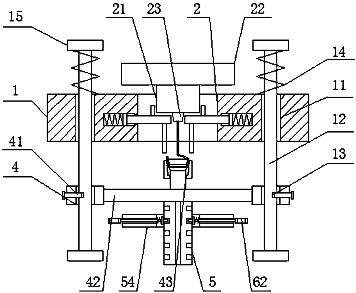
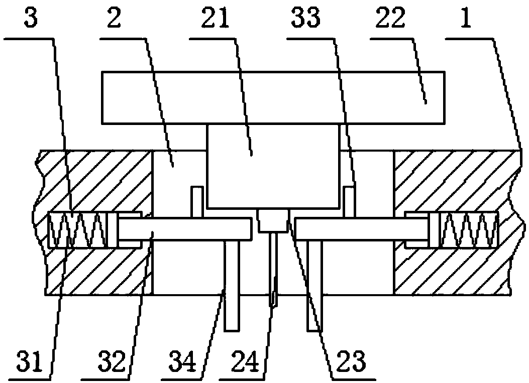
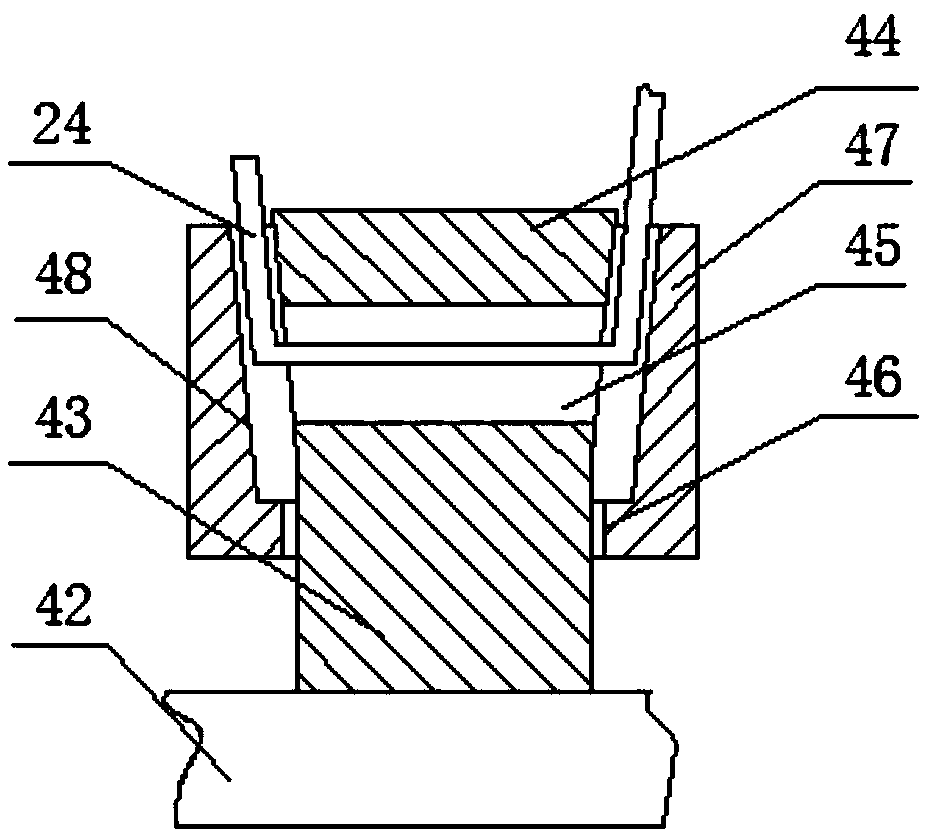
[0024] see Figure 1-5 , the present invention provides a technical solution: a pull-out test mechanism for various joints, including a support base 1, both sides of the support base 1 are provided with buffer sliding holes 11, and the inner surfaces of the buffer sliding holes 11 slide Connected with a sliding rod 12, the center of the outer surface of the sliding rod 12 is provided with a positioning hole 13, and the outer upper end of the sliding rod 12 is ...


PUM


Abstract

The invention discloses a drawing test mechanism for multiple joints. The drawing test mechanism comprises a support base; buffering slide holes are formed on the two sides in the support base; sliding rods are in sliding connection with the inside surfaces of the buffering slide holes; locating holes are formed on the outer surface centers of the sliding rods; buffering springs sleeve the upper ends of the outer surfaces of the sliding rods in a sliding form; limiting plates are arranged on the surfaces of the two ends of the sliding rods; an opening slot is formed in the support base; a socket is in sliding connection with the inside surface of the opening slot; a junction board is arranged on the upper surface of the socket; a plug is inserted into the lower surface of the socket; a pull rope is fixedly connected with the lower surface of the plug. The drawing test mechanism for multiple joints utilizes an adjusting plate tensioned by the spring in the opening slot to support the socket and utilizes the sliding rods supported by the springs to connect sliding rings in a sidling form, so that the use convenience and stability are greatly promoted and the safety and high efficiency of drawing test are guaranteed.

Description

technical field [0001] The invention relates to the technical field of pull-out testing, in particular to a pull-out testing mechanism for various joints. Background technique [0002] After the joint connection is fixed, a pull-out test is required to detect the stability of the joint connection and ensure product quality. The connector is placed upside down on the support seat with the open slot, but the size of the joint is inconsistent, and the internal size of the open slot cannot be adjusted, so it cannot stably support different sizes of connectors, and the positioning is inconvenient. It is convenient to fix the pull rope, which affects the efficiency of connection and positioning. At the same time, the weight plate is used to pull the plate by gravity, but it is not only inconvenient to add and fix the weight plate, which affects the efficiency and stability, but also when pulling out the plug. , are all rigid connections, without a buffer structure, which is likel...

Claims


Application Information

Patent Timeline
Patent Type & Authority Applications(China)
IPC IPC(8): G01N3/02G01N3/14
CPCG01N3/02G01N3/14G01N2203/0017G01N2203/0033
Inventor 刘华贵洪波
Owner JIANGXI AIKE IND
Why Eureka
Try Eureka